PISONICS
PS7110 Series
Inline Process Refractometer
Critical angle · Thin-layer interface · Indifferent to colour and turbidity
Product Overview
The PS7110 series measures the refractive index of the medium and converts it to concentration through a scale. Light travels from the prism towards the liquid; at the interface between the two, the part of the beam striking above the critical angle is totally reflected, and the part below it refracts into the liquid. A linear CCD array reads the position of the resulting shadow line, and each position corresponds to exactly one refractive index.
The measurement takes place in a thin layer at the prism face; the light never has to cross the flow channel. That single fact gives the method its strength — the colour, turbidity, bubbles and suspended solids of the medium do not enter the optical path, so they do not interfere. It also gives the method its constraint: the prism face must stay clean. Coating, crystals or abrasion change the reading directly, and the instrument does not raise a fault when they do. Media that foul need a cleaning strategy decided at the design stage, not added after the reading has started to drift.
A temperature sensor inside the probe measures the medium at the interface and feeds the temperature compensation. Refractive index and temperature are calibrated in standard units at the factory, unit by unit. On site the instrument supports RI verification and adjustment, self-service modelling and multi-point temperature compensation.
The PS7110 comes in three variants, A / B / C. They differ in prism material and process temperature; everything else is common.
How It Works
When light passes from an optically denser medium (the prism) towards a less dense one (the liquid), light above the critical angle is totally reflected and light below it refracts into the liquid. The refractive index of the prism is fixed, so the critical angle varies only with the refractive index of the liquid — measure the critical angle and you have the index.
A high-brightness LED is fibre-coupled into one side of the prism and reaches the prism-to-liquid interface along a designed path. The interface therefore carries an optical image made of a bright region and a dark one, and the angle at their boundary is the critical angle. A linear CCD array reads the position of that shadow line: every position corresponds to exactly one refractive index, and as concentration rises the index rises with it and the line shifts. From the index nD and the interface temperature T, the transmitter computes and displays concentration through the scale and the temperature-compensation model.
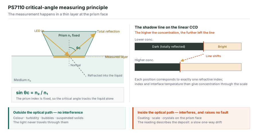
Figure 1 PS7110 critical-angle measuring principle
Why colour, turbidity and bubbles do not interfere. Transmission methods require the light to cross the whole channel, so colour, turbidity and bubbles all attenuate or scatter it. Critical-angle refractometry is different: the light reaches the prism-to-liquid interface and turns back, and the optical path is only the thin layer at that interface. Suspended particles, bubbles and colour never enter that path, so they do not move the shadow line.
The price of that property. The reading represents only the thin layer at the prism face. When the face is covered by a deposit, the instrument is measuring the deposit rather than the medium — and this does not raise a fault. It appears instead as a slow, one-way drift. That is why sensor status diagnostics exist, and why fouling duties need a cleaning unit specified up front.
Core Advantages
| No. | Feature | What it gives you |
|---|---|---|
| 1 | Critical-angle refractometry | No moving parts, no reagents, no waste stream; the reading comes straight from the geometry of the light |
| 2 | Thin-layer interface measurement | Indifferent to colour and turbidity — dark, cloudy and gas-bearing media read the same |
| 3 | Indifferent to flow regime | Unaffected by velocity, turbulence and flow pattern; a full pipe is not required, only that liquid washes over the prism face |
| 4 | Accuracy and resolution | Concentration ±0.1 %, refractive index ±0.0001; resolution 0.01 % and 0.00001 respectively |
| 5 | Calibrated unit by unit | Refractive index and temperature calibrated in standard units, nD 1.31 to 1.54 (0 to 100 Brix), so sensors agree with one another |
| 6 | Sensor status diagnostics | Continuous self-monitoring with the cause reported on failure; the "reading is still there but it describes the deposit" case can be located quickly from its signature |
| 7 | Adjustable on site | RI verification and adjustment, self-service modelling from sampled laboratory values, scale correction, multi-point temperature compensation |
| 8 | Sanitary construction | Tri-clamp connection, CIP and SIP capable, cleaning temperature −30 to 120 °C |
| 9 | Optional cleaning units | PS7110-CL1 ultrasonic cleaning unit keeps the face clean continuously; PS7110-CL2 high-pressure flushing unit flushes the face periodically |
| 10 | Three prism and temperature variants | A: high-strength optical glass, 0–60 °C. B: sapphire, 0–70 °C. C: sapphire, −10–100 °C |
| 11 | Analogue and digital output | 4–20 mA together with RS485 / RS232 / USB, so a DCS or PLC and a host computer can be connected at the same time |
| 12 | Intrinsically safe option | Ex ia IIC T6 Ga; IP68 for the wetted parts |
How It Differs From the Other Inline Methods
Each of the mainstream routes to inline concentration has its own hard boundary. The table below compares them by the failure modes that actually show up on site, so you can tell which route a given duty belongs on.
| Dimension | PS7110 refractive index | Sound velocity / absorption spectroscopy / density |
|---|---|---|
| Optical path | Thin layer at the prism face | Across the channel or the full cross-section |
| Colour and turbidity | No effect | Spectroscopy is sensitive |
| Bubbles | Outside the optical path, little effect | Both spectroscopy and sound velocity are sensitive |
| Flow regime and velocity | No effect; the face only has to be wetted | Most methods need a full pipe and a minimum velocity |
| A clean surface | The decisive precondition | Not applicable to density methods |
| Multiple components | Cannot separate components of similar index | Spectroscopy can quantify them separately when the matrix is stable |
Refractive index and sound velocity often reach the shortlist together. The test is simple: if the medium is dark, cloudy or gas-bearing and the concentration-to-index relationship is monotonic, choose refractive index. If the medium is clean, higher concentration resolution is needed and there is no fouling risk, choose sound velocity (PS7020). If several components have to be separated or the identity of the medium confirmed, choose absorption spectroscopy (PS7100).
Scale and Calibration
Refractive index is what the instrument measures directly; concentration is what the scale derives from it. Index and temperature are calibrated at the factory. The concentration scale, however, depends on the medium.
Brix is a scale referenced to sucrose in water. When the medium is not a sucrose solution, its own concentration-to-index relationship has to be established, together with multi-point temperature compensation. That work can be done by the factory before delivery, or by the user on site through self-service modelling.
A scale built for one medium must not be used to read another liquid — the same refractive index does not mean the same concentration. Where one instrument has to read several media in turn, each needs its own scale, selected when the medium changes.
Typical Applications
- Food and beverage — sucrose, fruit purée, jelly, soft drinks, fructose, juice and stock during production
- Sugar and brewing — syrup concentration, glucose, concentration through beer production
- Dairy — solids content in milk and dairy products
- Chemicals and petrochemicals — sulphuric, hydrochloric and phosphoric acid, sodium hydroxide, ammonia, urea, surfactants, ethylene glycol, hydrogen peroxide, sodium hypochlorite, methanol, ethanol
- Cutting and cooling fluids — mix ratio of cutting fluid, coolant and emulsion
- Pharmaceuticals and traditional medicine — DMF, DMAC, concentrated extracts, alcohol-extraction steps
- Polymers and materials — PVOH, polyurethane, slurries, gelatine, collagen peptides
- Other — sodium carbonate and glycerine solutions
For duties not listed, send the composition, concentration range, working temperature and pressure, and whether coating or abrasive particles are present, and we will assess suitability and the scale approach.
Wetted Material Compatibility
Depending on the chemistry and concentration of the liquid, the B and C variants accept PTFE, Hastelloy, titanium or tantalum wetted parts. The table below is guidance for common media — it is not exhaustive, and unusual duties should be reviewed with an engineer.
| Class | Medium | Formula | Conc. (%) | 316L | Hastelloy | Titanium | PTFE |
|---|---|---|---|---|---|---|---|
| Acid | Hydrochloric acid (HF-free) | HCl | 0–40 | × | ○ | × | ☆ |
| Sulphuric acid | H₂SO₄ | 0–50 | ○ | ☆ | ○ | ☆ | |
| Sulphuric acid | H₂SO₄ | 50–75 | × | ○ | × | ☆ | |
| Sulphuric acid | H₂SO₄ | 75–98 | ○ | ☆ | ○ | ☆ | |
| Nitric acid | HNO₃ | 0–100 | ○ | ○ | ○ | ☆ | |
| Phosphoric acid | H₃PO₄ | 0–98 | × | × | × | ☆ | |
| Alkali | Sodium hydroxide | NaOH | 0–50 | ☆ | ☆ | ☆ | ☆ |
| Potassium hydroxide | KOH | 0–50 | ☆ | ☆ | ☆ | ☆ | |
| Calcium hydroxide | Ca(OH)₂ | 0–50 | ☆ | ☆ | ☆ | ☆ | |
| Salt | Sodium chloride | NaCl | 0–50 | × | ☆ | ☆ | ☆ |
| Ammonium chloride | NH₄Cl | 0–50 | × | ☆ | ☆ | ☆ | |
| Ammonium sulphate | (NH₄)₂SO₄ | 0–50 | × | ☆ | ☆ | ☆ | |
| Other | Urea | (NH₂)₂CO | 0–100 | ☆ | ☆ | ○ | ☆ |
| Sodium hypochlorite | NaOCl | 0–16 | × | ○ | × | ☆ | |
| Hydrogen peroxide | H₂O₂ | 0–90 | ☆ | ☆ | ○ | ☆ |
☆ recommended ○ usable within stated concentration and temperature limits × not recommended. Tantalum is also available as a wetted material; its compatibility is assessed per medium, concentration and temperature and is not tabulated above.
Model Variants
| Item | PS7110-A | PS7110-B | PS7110-C |
|---|---|---|---|
| Concentration range | 0.0 – 90 %Brix | 0.0 – 100 %Brix | 0.0 – 100 %Brix |
| Refractive index range | 1.33299 – 1.51782 | 1.33299 – 1.57041 | 1.33299 – 1.57041 |
| Process temperature | 0 – 60 °C | 0 – 70 °C | −10 – 100 °C |
| Prism material | High-strength optical glass | Sapphire | Sapphire |
| Optional wetted materials | — | PTFE / Hastelloy / titanium / tantalum | PTFE / Hastelloy / titanium / tantalum |
Technical Specifications
| Item | Specification |
|---|---|
| Model | PS7110 series inline process refractometer (variants A / B / C) |
| Measuring principle | Critical-angle refractometry; CCD array reads the shadow-line position |
| Measured quantities | Refractive index, temperature, concentration, Brix (or another scale) |
| Displayed values | Refractive index nD, Brix (temperature-compensated for sucrose), concentration Conc, temperature °C |
| Available outputs | Beyond the displayed values, mass concentration, solids content and density can be derived through the scale; refractive index nD can also be output directly |
| Accuracy | Concentration ±0.1 %; refractive index ±0.0001; temperature ±0.5 °C |
| Resolution | Concentration 0.01 %; refractive index 0.00001; temperature 0.1 °C |
| Concentration range | A: 0.0 – 90 %Brix; B / C: 0.0 – 100 %Brix |
| Refractive index range | A: 1.33299 – 1.51782; B / C: 1.33299 – 1.57041 |
| Factory calibration span | nD = 1.31 to 1.54 (0 to 100 Brix), calibrated unit by unit |
| Built-in scale | Brix, temperature-compensated for sucrose |
| Data processing | Sensor status diagnostics, RI verification and adjustment, self-service modelling, multi-point temperature compensation, scale correction |
| Custom scales | Built to order from a model for the specified medium |
| Process temperature | A: 0 – 60 °C; B: 0 – 70 °C; C: −10 – 100 °C |
| Ambient temperature | −10 to 100 °C |
| Cleaning temperature | −30 to 120 °C; CIP and SIP capable |
| Pressure rating | ≤ 1.5 MPa at the prism face |
| Power supply | DC 24 V standard; AC 100–240 V, 50/60 Hz, 30 VA optional |
| Supply tolerance | Within ±10 % of rated voltage |
| Signal output | 4–20 mA / RS485 / RS232 / USB |
| Cable length | 2 m standard, extendable to 200 m |
| Display | 1.4-inch on-board display |
| Prism material | A: high-strength optical glass; B / C: sapphire |
| Wetted materials | SS316L plus prism; B / C accept PTFE / Hastelloy / titanium / tantalum |
| Process connection | Compact tri-clamp; flange DN25 / DN50 / DN65 / DN80 optional |
| Ingress protection | IP68 for the wetted parts |
| Hazardous area | Ex ia IIC T6 Ga |
| Net weight | Approx. 1.0 kg |
| Overall dimensions | Depend on the process connection; the order drawing governs |
Choosing the Variant
| What decides it | Variant |
|---|---|
| Process temperature 0 – 60 °C, concentration no higher than 90 Brix, medium not corrosive | PS7110-A |
| Full 0 – 100 Brix span needed, or the medium attacks optical glass | PS7110-B |
| Process temperature below 0 °C or above 70 °C | PS7110-C |
| The medium attacks SS316L | B or C with PTFE, Hastelloy, titanium or tantalum |
Cleaning and Accessories
A clean prism face is the precondition for a trustworthy reading. Media that coat or crystallise need a cleaning strategy decided at the design stage, not added after the reading has started to drift.
| Code | Item | Application |
|---|---|---|
| — | CIP / SIP | Routine cleaning in sanitary processes; cleaning temperature −30 to 120 °C |
| PS7110-CL1 | Ultrasonic cleaning unit | Keeps the prism face clean continuously; for media that form films or coatings |
| PS7110-CL2 | High-pressure flushing unit | Periodic flushing of the face with high-pressure gas or liquid; for crystallising or particle-depositing duties |
| PS7110-MT1 | Small-bore adapter | Lines of 2 inch and below |
| PS7110-MT2 | Tee with sight glass | Where the face has to be checked visually |
| PS7110-MT3 | Cross with sight glass | Where a flushing or sampling branch is needed as well |
| PS7110-MT4 | Sanitary adapter | Food, dairy and pharmaceutical processes |
| PS7110-SY1 | Remote display controller | Separates display from sensor for points that are hard to reach |
| PS7110-SY2 | Multi-channel acquisition system | Up to 120 channels for centralised management of several points |
| PS7110-SY3 | Terminal data acquisition system | Central acquisition and archiving of field data |
| PS7110-SY4 | Wireless transmission module | For points where cabling is impractical |
Product Configuration
An order code is the variant code plus any accessory codes. Accessory codes use two functional letters plus a serial number: CL for cleaning, MT for mounting, SY for system. They do not collide with the single-letter variant codes and can be listed alongside them on an order.
Example: PS7110-B + PS7110-CL1 + PS7110-MT4
→ variant B (sapphire prism, 0–70 °C, 0–100 Brix) with an ultrasonic cleaning unit and a sanitary adapter.
To configure, send the composition of the medium, the concentration range, the working temperature and pressure, the line size and the mounting position, and whether coating, crystals or abrasive particles are present.
Installation Schemes
The PS7110 reads the refractive index of a thin layer of liquid at the prism face, so a trustworthy reading rests on two things: whether the face is always washed by liquid that represents the process, and whether it is clean. Installation settles the first; cleaning settles the second.
The four mounting schemes differ in maintenance cost and in how steady the measuring conditions are, not in the measurement itself. Which one suits a plant comes down to whether the line can be stopped, and how much the steadiness of the reading is worth.
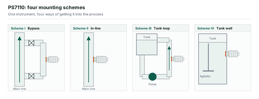
| Scheme | What it is | Trade-off |
|---|---|---|
| I Bypass | A valved bypass off the main line, with the probe on the bypass | Close the valves and service it without stopping the main line; the recommended scheme, at the cost of extra fittings and valves |
| II In-line | The probe sits directly in the main line | Cheapest to fit; cleaning, calibration and service all need a shutdown |
| III Tank loop | A pump draws from the tank and returns through a loop, with the probe downstream of the pump | Constant flow, the steadiest measuring conditions and the best reading; the highest cost |
| IV Tank wall | The probe enters through the tank wall with its face in the liquid | Simplest arrangement; needs the liquid to keep circulating and the agitator to stay clear of the window |
How to choose: start with whether the line can be stopped. If it can, fit in-line. If it cannot, use the bypass. Where the steadiness of the reading matters most and the budget allows, use the tank loop; and where the measuring point is on a vessel, use the tank wall.
Process connections fall into three cases by pipe size and vessel type:
| Case | How it connects |
|---|---|
| Medium and large pipe | Tri-clamp or flange straight into the line, with the face inside the bore and never pointing down |
| 2″ and below | Through the small-bore adapter (PS7110-MT1), so the liquid fully covers the face |
| Vessel or tank wall | Into the tank wall with the face immersed; the liquid must keep circulating and the agitator must stay clear of the window |
Probe Orientation
In a pipe or a vessel alike, the orientation of the prism face is not negotiable: it must never point downward. A downward face collects deposit, and deposit raises no fault — it shows up only as a slow one-way drift. For the same reason the probe does not belong at the top of a pipe, where gas collects: once liquid no longer covers the face, the reading stops meaning anything.
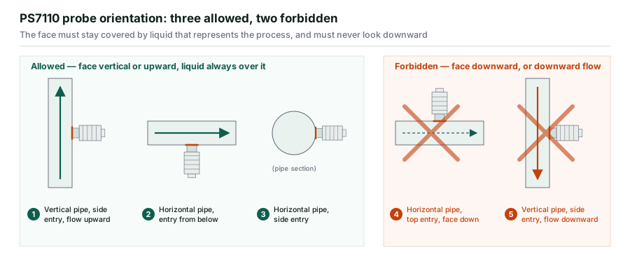
| Arrangement | Verdict | Why |
|---|---|---|
| (1) Vertical pipe, side entry, flow upward | Allowed | The face is vertical, and an upward vertical run stays full and steady |
| (2) Horizontal pipe, entry from below (face up) | Allowed | The face looks upward and liquid stays over it |
| (3) Horizontal pipe, side entry | Allowed | The face is vertical, which satisfies the same requirement |
| (4) Horizontal pipe, top entry (face down) | Forbidden | A downward face collects deposit, and raises no fault while it does |
| (5) Vertical pipe, side entry, flow downward | Forbidden | A downward run drains or runs part-full and the prism is left uncovered |
(1) and (5) are the same fitting — only the flow direction differs. On a retrofit into existing pipework this is the easy one to miss: the tapping ends up in a defensible place and the flow turns out to run the wrong way. Neither mistake raises a fault: (4) drifts slowly one way, and (5) stops meaning anything as soon as the pump stops.
Installation
Beyond orientation, the following apply to the location and the wiring:
- Media that can carry grit or abrasive particles must have them filtered out upstream, or the detection window will be worn away.
- Liquid in a vessel must be circulating, and the agitator must not be able to reach the measuring window.
- Avoid positions with heavy vibration; avoid direct sunlight, rain and heavy dust.
- A safe and reliable earth is required, and the analogue output needs a shielded cable or an enclosure earth. Beyond about 5 m, use the RS485 digital signal.
- When the instrument is out of service for a long period, switch it off, keep crystals from forming on the window and keep the window clean.
Reading the Symptoms on Site
Failures of the refractive-index method rarely stop the instrument. They usually appear as a reading that is still there but now describes the deposit rather than the medium. The conditions below do not normally raise a fault code, but their signatures are distinctive enough to locate the problem quickly.
| Symptom | Most likely cause |
|---|---|
| Slow one-way drift, unusually smooth curve | Coating, scale or crystals on the prism — the instrument is reading the deposit, not the medium |
| Sudden step, then no longer follows the process | The face is covered by gas, or the level has dropped and no longer covers the prism |
| Whole reading offset by a constant amount | The scale does not match the current medium, or the index zero needs RI verification |
| Reading swings with temperature | Compensation points do not cover the present temperature range, or the temperature is swinging sharply |
| Noise increasing and not recovering | The prism face is being abraded; check the upstream filtration |
The condition of the prism face is the single precondition for a trustworthy reading. Putting "look at the face" into the routine inspection is worth more than any coefficient correction applied afterwards.
Optical Precision · Real-Time Concentration
※ For non-standard spans, special wetted materials, hazardous-area versions or a detailed configuration proposal, contact a Pisonics engineer.