PISONICS
PS7110 Series
Inline Process Refractometer
Critical angle · thin-layer interface · indifferent to colour and turbidity
Inline Concentration Monitoring for PAG Polymer Quenchants
—— Induction hardening · through hardening · quench-tank circulation ——
【Measured: quenchant concentration (%) / refractive index nD】
Inline concentration monitoring for PAG polymer quenchants
1. Process background
The cooling rate of a water-soluble polymer quenchant (mostly polyalkylene glycol, PAG) is set mainly by its concentration: too low and cooling is too fast, raising residual stress and distortion and, at worst, cracking; too high and cooling is too slow, risking low hardness.
And concentration drifts by nature: evaporation concentrates it, drag-out on the parts depletes it, and make-up adds its own error. The usual shop-floor practice is to read Brix on a handheld refractometer, multiply by the supplier's refractometer factor, and check against kinematic viscosity — which tells you refractometry is already the method on this duty. What the PS7110 does is make the same quantity continuous: the reading is on the same basis as the handheld, directly comparable, and it can go to a PLC to close the make-up loop.
2. Three traps for a refractometer on quenchant
1. The factor drifts with contamination. Refractive index does not know where it comes from: inorganic salts from hard water, dragged-in cleaners or other water-soluble fluids, and oil all raise the reading once dissolved, so the factor usually goes down. Left uncorrected, the displayed concentration reads higher than the actual polymer concentration — the make-up loop adds too little, the real concentration keeps falling, and low concentration is exactly the cracking risk. Carbon fines and most insoluble solids have little effect.
2. Degradation is invisible. Over long service the polymer degrades and the cooling behaviour changes, but the refractometer reading may not show it. Cooling characteristics are checked by cooling-curve testing (ASTM D6482) on the supplier's schedule; ASTM D6666 lists what to evaluate.
3. Inverse solubility decides where the probe goes. PAG comes out of solution at higher temperature — that is how it forms a film on the hot part and controls cooling. So the probe must not sit near the quench zone, and the bath must stay below its cloud point; once the liquid separates into two phases the refractometer reading means nothing.
3. What it can and cannot do
It can:
- Track concentration drift continuously — evaporation, drag-out and make-up error all become visible
- Measure the same quantity as the handheld refractometer, so the readings are directly comparable
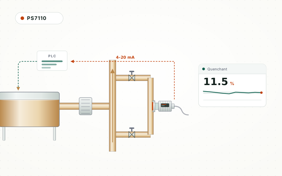
- Send 4–20 mA and RS485 (Modbus RTU) to a PLC to close the automatic make-up loop
It cannot (stated here so nobody buys the wrong thing):
- Tell polymer from dissolved contaminants — check against kinematic viscosity (ASTM D445) periodically and correct the factor
- See polymer degradation — that needs cooling-curve testing
- Measure pH or bacteria — measure those separately; they do not show in the refractive index
- Run unfiltered on a bath carrying scale and grit — abrasive particles must be removed upstream; the detection window is a wear part
4. Selecting the PS7110
| Grade | Prism | Process temp. | RI range | Factory scale | Fits |
|---|---|---|---|---|---|
| PS7110-A | High-strength optical glass | 0–60 °C | 1.33299–1.46510 | 0–70 %Brix | Cooler baths with a modest range |
| PS7110-B | Sapphire | 0–70 °C | 1.33299–1.51782 | 0–90 %Brix | Default for most quench tanks (a PAG bath has to run below its cloud point anyway) |
| PS7110-C | Sapphire | −10–100 °C | 1.33299–1.57041 | 0–100 %Brix | Warmer baths, or lines that may fall below 0 °C in winter |
Put the probe on a bypass from the quench-tank circulation pump discharge, after the filter and after the cooler; not in the quench zone and not next to the parts in the tank.
General specification:
| Item | Specification (data sheet Rev. B) |
|---|---|
| Measured value | Refractive index nD; converted to concentration by a scale (%Brix, or a wt% scale built for the medium) |
| Accuracy | RI ±0.0001; Brix ±0.1 %; temperature ±0.5 °C |
| Resolution | RI 0.00001; Brix 0.01 %; temperature 0.1 °C |
| Measuring interval | 2–60 s, settable |
| Pressure rating | Detection surface ≤ 1.5 MPa |
| Cleaning temperature | 0–120 °C, CIP / SIP capable |
| Wetted materials | SS316L + prism; Hastelloy, titanium or tantalum optional on grades B / C |
| Process connection | Clamp (Ø77.5 mm ferrule); custom tee / cross, cross in DN25 / 50 / 65 / 80 |
| Outputs | 4–20 mA; RS485 (Modbus RTU) |
| Power / ambient | DC 24 V; −10 to 70 °C |
| Hazardous area | Ex ia IIC T6 Ga (intrinsically safe) |
5. Building the scale
The scale belongs to your quenchant product: start from the supplier's refractometer factor at commissioning, then correct it with the concentration found by kinematic viscosity (ASTM D445); check it again after a product change, a change in make-up water, or a contamination event. On site the PS7110 supports RI calibration, self-built models from laboratory samples and multi-point temperature compensation, so the factor is corrected without returning the instrument.
6. Installation and upkeep
- Never mount the detection face pointing down — deposits build up, and a deposit does not raise a fault; it shows only as a slow one-way drift
- On a vertical line the flow must be upward — a downcomer drains when the pump stops, the prism is no longer wetted and the reading means nothing
- On a horizontal line insert from below (face up) or from the side (face vertical); inserting from the top is not allowed
- Mount on a bypass of the circulation loop, with a valve at each end so it can be isolated
- Filter upstream: scale, grit and other abrasive particles must be removed
- Do not sample from the surface layer of floating oil and foam: oil films the prism; place the probe in the full-bore pump discharge
- Decide the cleaning at design stage — ultrasonic or high-pressure flushing units are available
7. Before you order
- Quenchant brand and grade, and the supplier's refractometer factor.
- Target concentration and allowed band.
- Bath temperature range, and the product's cloud point.
- Likely contamination sources: hard water, cleaners, carried-over cutting fluid, oil, salts.
- Filtration fineness and how much grit the bath carries.
- Bypass line size and connection type.
- Number of measuring points: one per tank, or several tanks.
What this page is: a method and selection note, not a case study. The PS7110 has no publishable installed data in this industry yet, so there are no unit counts, saving percentages or payback periods here — we do not invent those. The numbers on the page are of two kinds only: the instrument's own specification, and published properties and standards, plus order-of-magnitude estimates derived from them.
Conclusion
PISONICS covers six principle families (ultrasonic, tuning fork, Coriolis, optical, microwave, differential pressure) for inline density and concentration. Quenchant, like cutting fluid, is already measured by refractometry on the shop floor; going inline turns a spot check into a continuous reading — but it does not replace the viscosity check or the cooling curve. Further reading: cutting fluid and coolant ratio monitoring, ethylene / propylene glycol concentration monitoring, Optical concentration meter principle.


