PISONICS | Xi’an Pisonics
PS7010 Series
Clamp-on Ultrasonic Density Meter
Clamp-on · no pipe penetration · retrofit while running
Product Overview
The PS7010 series clamp-on ultrasonic density meter is a non-nuclear inline slurry density meter developed by Xi’an Pisonics (PISONICS) for the three field constraints of “no pipe penetration, no hot work, no shutdown”. Transmitter and receiver are mounted on opposite sides of the pipe, and the instrument resolves in real time the energy the ultrasonic beam loses in crossing the medium, from which the density and concentration of the slurry are derived.
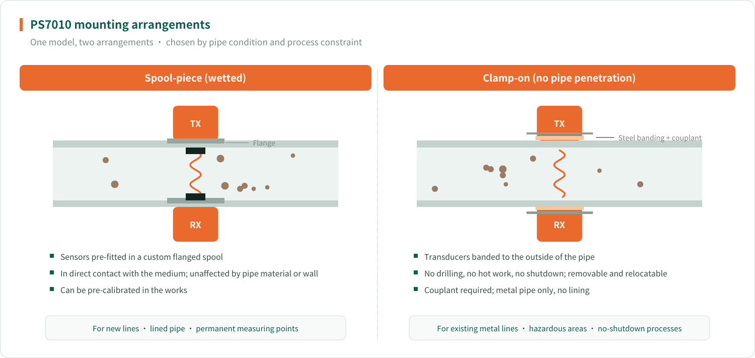
Two mounting arrangements are available: spool-piece (wetted, in-line) and clamp-on (banded to the pipe, no penetration). Clamp-on sensors do not touch the medium and do not breach the pipe, so they can be deployed on an existing line without a shutdown and removed or relocated at any time — this is what distinguishes a clamp-on arrangement from an insertion one.
How It Works
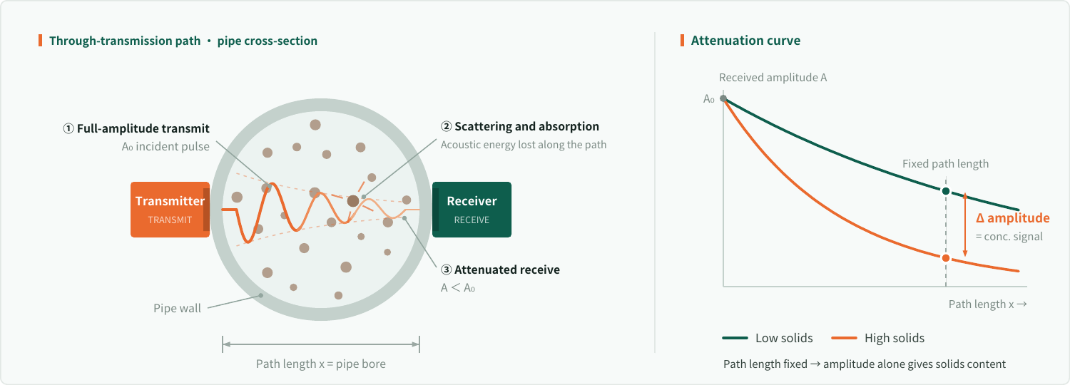
Acoustic attenuation rests on a direct physical fact: when ultrasound crosses a slurry, the solid particles scatter and absorb part of the acoustic energy, so the signal reaching the receiver decays exponentially. The higher the solids content, the stronger the attenuation and the weaker the received signal. With the path length fixed, measuring the attenuation coefficient α gives the concentration.
The attenuation coefficient has three contributions: scattering by the particles, viscous and thermal absorption in the medium, and a frequency-dependent term — the higher the frequency, the stronger the attenuation. That term sets the upper limit on usable path length and is the underlying reason for the bore range of the PS7010.
Scattering grows with the cube of particle diameter: double the particle size and scattering increases roughly eightfold. Particle size distribution therefore affects an attenuation measurement more directly than a reflective one, and the instrument must be recalibrated whenever the distribution changes appreciably.
Core Advantages
Technology / feature | Customer benefit |
Through-transmission attenuation measurement | Two sensors, one transmitting and one receiving; the energy lost in crossing the slurry is directly related to the solids content. The acoustic path spans the full chord of the pipe, so the reading is a cross-sectional average rather than a single point |
Clamp-on mounting, no pipe penetration | No drilling, no hot work, no shutdown; minimal work and short outage on an existing line. The sensors do not touch the medium, so there is no erosion, no leak path and no wetted-material compatibility question |
Spool-piece and clamp-on in one model | One model covers both arrangements: spool-piece for new lines and lined pipe, clamp-on for existing metal lines, hazardous areas and processes that cannot be stopped |
Removable and relocatable | Clamp-on sensors are held by steel banding and can be removed and moved to another measuring point at any time — suitable for temporary monitoring, process surveys and multi-point rounds |
Non-nuclear, zero radiation | No gamma radiation protection, and none of the licensing, registration, annual inspection or decommissioning burden |
Statistical outlier rejection and adaptive filtering | Selectable outlier-rejection strategies combined with one of four output filters, suppressing reading jumps caused by flow pulsation |
Online aeration diagnostics | A 0–100 aeration index and a bubble flag are output with the primary variable, so a high reading can be attributed either to a genuine rise in concentration or to entrained air, and the attribution is traceable |
Five parallel interfaces | 2 × 4–20 mA + RS485 Modbus-RTU + HART + 4G + Bluetooth; DCS, PLC, handheld communicator, mobile device and cloud can all be connected at the same time |
NAMUR NE43 compliant output | 3.5 mA low alarm on fault (default ex works), 3.8 / 20.5 mA out-of-range indication band; fault, out-of-range and valid measurement stay clearly distinguishable at the DCS |
One operating model across instrument, desk and cloud | The instrument, the PC software and the Pisonics cloud platform share one and the same set of Modbus registers, supporting remote configuration, guided calibration and over-the-air firmware update (OTA) |
Ex / CE certification | Ex d IIC T6 Gb available as an option; EU CE certified |
Aerated Conditions: Limits and Interpretation
The measured quantity of an attenuation measurement is the strength of the received signal, and bubbles weaken that signal by scattering and blocking the beam. Entrained air and solids therefore act in the same direction on signal amplitude and cannot be separated directly, and entrained air biases the density reading systematically high. This is the opposite of the reflective PS7000 and must not be interpreted in the same way in the field.
The instrument continuously outputs a 0–100 aeration index and a bubble flag. The index is derived from the stability of the measurement process itself rather than from the absolute signal strength, so it does not depend on whether the signal grows or falls — which is precisely why it remains valid in a through-transmission geometry.
For heavily aerated duties, select the PS7000 ultrasonic slurry density meter instead: it is reflective and short-path, so bubbles do not accumulate attenuation along a long through-transmission path. This is the main selection boundary between the two models.
Typical Applications
Industry | Typical measuring points |
Chemical / fine chemical | Acid and alkali concentration, reactor discharge concentration, catalyst slurry density |
Salt chemistry / potash | Saturated brine concentration, crystallisation liquor density, inline measurement on brine transfer lines |
Sugar / pulp and paper | Syrup and cane juice concentration, black and white liquor concentration, starch slurry density |
Food / brewing | Juice and concentrate density, fermentation mash concentration, process concentration in dairy |
Mining / mineral processing | Feed and discharge density of degassed slurry, tailings transport density |
Hazardous areas / retrofits | Work without hot permits in flammable areas, retrofit onto existing lines, temporary or permanent monitoring on processes that cannot be stopped |
Assessing Clamp-on Feasibility
A clamp-on measurement is made through the pipe wall, which therefore becomes part of the acoustic path, and feasibility is decided by the pipe. Please provide with your enquiry: pipe material and nominal bore, measured wall thickness, whether a lining is present, the condition of the outer surface, whether insulation is present and may be opened locally, the straight run available at the intended position, and the medium, concentration range, particle size distribution, entrained air, temperature and velocity.
A clamp-on arrangement requires metal pipe (carbon steel, stainless steel or copper alloy) with uniform wall thickness and consistent material, no internal lining, and an outer surface that can be dressed; acoustic couplant is applied and the sensors are held by steel banding. A site coupling test must be completed and the signal quality recorded before installation — a position that has not passed the coupling test must not be used to judge performance, and this is the greatest difference between a clamp-on and an insertion arrangement.
Technical Specifications
Item | Specification |
Model | PS7010 series (ultrasonic acoustic attenuation) |
Measuring principle | Ultrasonic through-transmission attenuation; two sensors, one transmitting and one receiving |
Sensor configuration | 1 × transmitter + 1 × receiver, mounted opposite one another on the pipe |
Medium | Two-phase solid/liquid slurry, solutions, syrups, black liquor and similar; low entrained air required |
Measuring range | 0–80 % mass concentration, calibrated to the medium; the practical upper limit is set by bore and by attenuation at high solids, and is confirmed by Pisonics against the duty |
Accuracy | ±1 % FS; the typical figure after calibration on the actual liquid is better than this, as stated on the calibration certificate |
Primary variable | Density (g/cm³ or kg/m³), mass concentration, volume concentration, degrees Baumé, solids content (g/L) |
Diagnostic values | Aeration index (0–100) and bubble flag, received signal energy, signal quality, sensor temperature, fault status word |
Power supply | AC 220 V (AC 100–240 V, 50/60 Hz wide-range input) or DC 24 V; both are standard |
Power consumption | ≤ 1 W |
Ambient temperature | −30 to +60 °C |
Medium temperature | 0 to 80 °C |
Humidity | ≤ 98 %RH, non-condensing |
Nominal bore | DN50 to DN500 |
Mounting | Clamp-on (steel banding, no pipe penetration) or spool-piece (custom flanged measuring spool); in both cases the transmitter enclosure is remotely wall-mounted |
Pipe wall requirements (clamp-on) | Metal pipe (carbon steel, stainless steel, copper alloy) with uniform wall thickness and consistent material, no internal lining, outer surface able to be dressed |
Acoustic coupling | Clamp-on requires acoustic couplant; a site coupling test must be completed before installation |
Sensor cable | Standard 5 m; other lengths on request |
Optional lining | Spool-piece: PTFE / rubber / ceramic, specified to the duty |
Temperature sensing | PT1000 sensor temperature (22-bit Σ-Δ acquisition with open-circuit and short-circuit diagnostics) plus an on-board digital temperature sensor |
Analogue output | 2 × 4–20 mA to NAMUR NE43; output variable, range endpoints, correction coefficients and fault current are set independently for each channel |
Digital communication | RS485 Modbus-RTU, slave address 1–247, baud rate 1200 / 2400 / 4800 / 9600 / 19200 / 38400 / 57600 / 115200 bps (57600 ex works), transmission distance approx. 500 m |
HART | HART 5 slave, Bell 202 FSK (1200 bps) superimposed on 4–20 mA loop 1 |
Bluetooth | Bluetooth 5.4 BLE; live readings and the complete parameter set can be handled from a phone or tablet |
Remote transmission | 4G / DTU connection to the Pisonics cloud platform (option) |
Fieldbus | Profibus-DP (option) |
Display and operation | OLED display window, bilingual Chinese/English menu, infrared remote control; remote digital display available as an option |
Field calibration | Multi-point linear regression Y = aX + b, up to 20 points; from 3 points onward accepted automatically on r² ≥ 0.8 |
Factory calibration | 40 independent calibration sets, each with up to 16 concentration points × 15 temperature points, retained in Flash |
Data storage | 360 records in the instrument (logging interval configurable; 20 min by default, about 5 days). Telemetry is retained for 90 days once connected to the cloud platform |
Firmware update | Dual-slot OTA with CRC-32 whole-image verification and device-type identity check; the existing firmware is retained automatically if an update fails. Remote update from the cloud is supported |
Ingress protection | IP65 |
Hazardous area | Ex d IIC T6 Gb (option, to be specified when ordering) |
Certification | EU CE (certificate supplied with the instrument) |
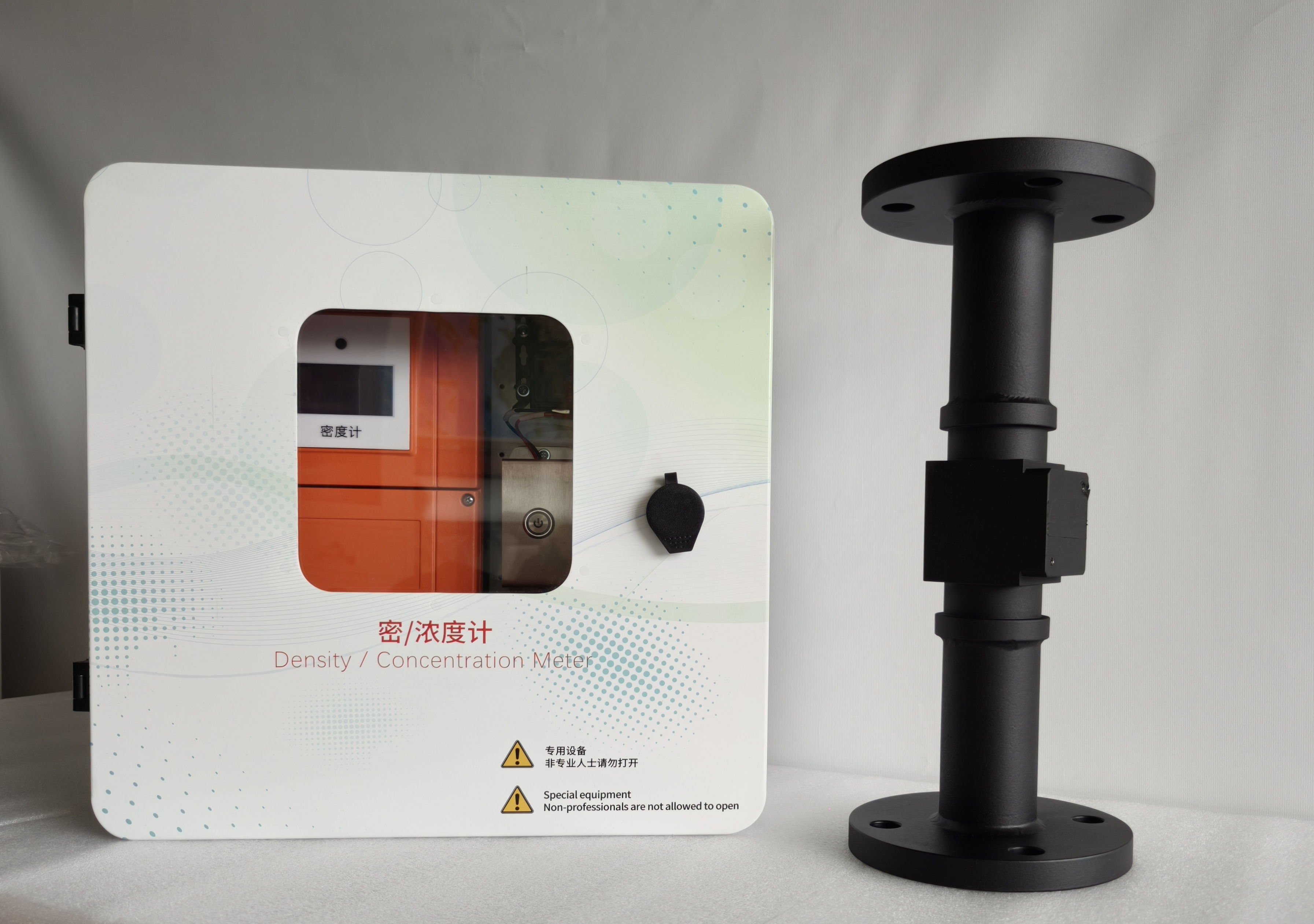
Transmitter enclosure | 400 (W) × 400 (H) × 180 (D) mm |
Transmitter weight | approx. 15 kg |
※ For non-standard ranges, spool-piece linings, explosion-proof versions or a clamp-on feasibility assessment, please contact a Pisonics engineer. The PS7010 Technical Specification is the authoritative source for the complete data.