PISONICS | Xi’an Pisonics
PS7020 Series
Inline Ultrasonic Concentration Meter
Integral spool · no moving parts · inline concentration
Product Overview
The PS7020 series inline ultrasonic concentration meter determines concentration from a quantity that can be measured directly: the time an ultrasonic pulse takes to cross the medium. The acoustic path length is fixed by the mechanical structure of the measuring spool, so the transit time gives the sonic velocity, which is then converted to concentration or density through a calibration table established on the actual liquid.
Unlike acoustic impedance (PS7000) and acoustic attenuation (PS7010), which both rely on echo amplitude, a sonic velocity measurement uses the arrival time of the signal rather than its amplitude on arrival. That makes it insensitive to amplitude-type degradation such as a fouled sensor face, aged coupling or gain drift — and it also sets the limits of its applicability: where the solids content is high enough to scatter the beam severely, the PS7000 should be selected instead. The instrument is of integral construction, with the measuring spool and the transmitter in one body, and has no moving parts and no consumables.
How It Works
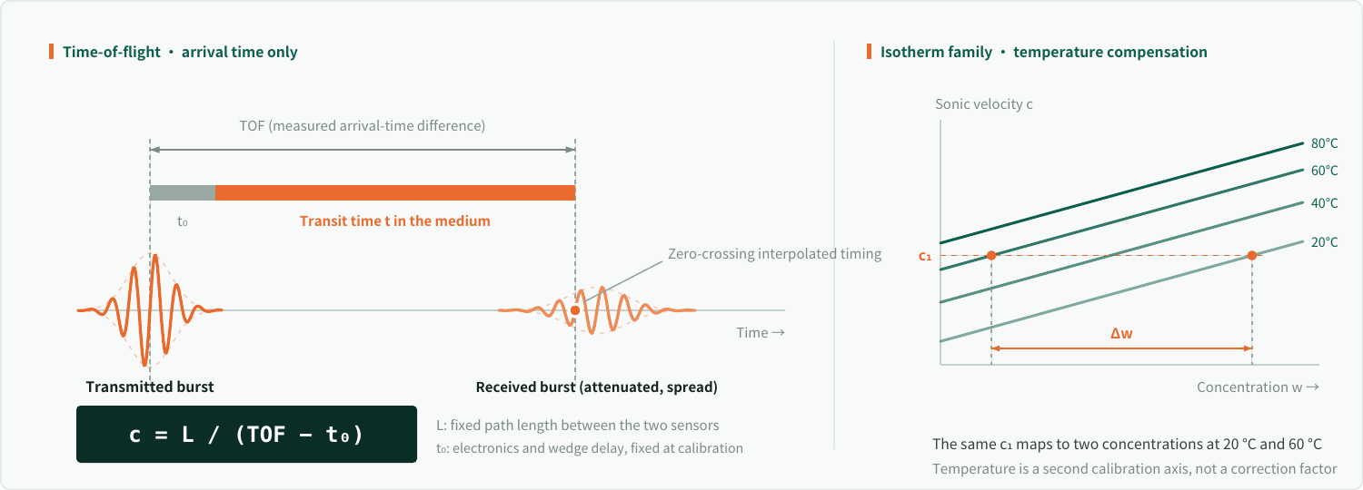
Two sensors are mounted opposite one another on the measuring spool, one transmitting and one receiving. The transmitter emits a burst of ultrasonic pulses and the receiver records its arrival time; subtracting the fixed delay contributed by the electronics and the wedges gives the actual transit time through the medium, which divided into the fixed path length gives the sonic velocity.
The arrival time is established by zero-crossing interpolation rather than by an envelope threshold: the position at which the received waveform crosses zero is subdivided below the sampling interval, giving a timing resolution far finer than the sampling period. This is where the sonic velocity resolution comes from, and it is also why the method is insensitive to changes in echo amplitude — a change in amplitude does not move the zero crossing.
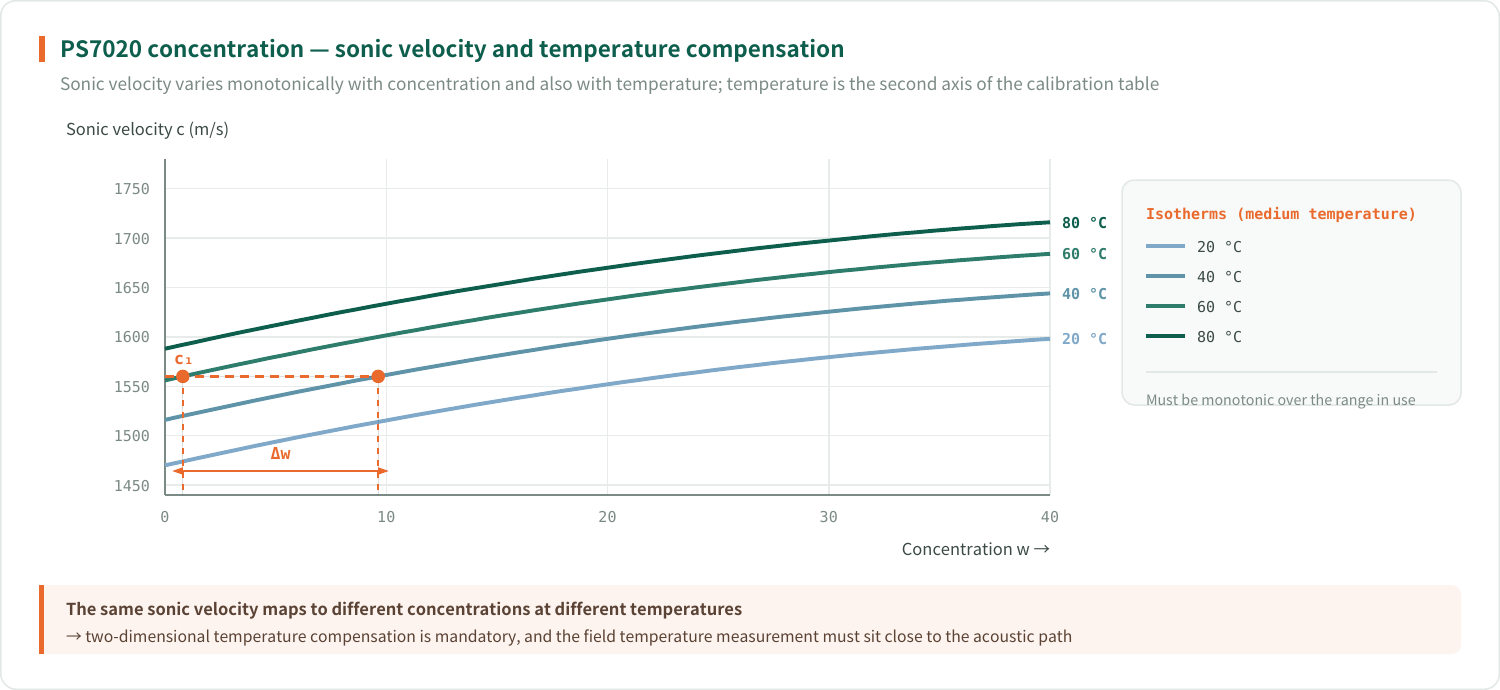
Temperature is not a “correction term” but an independent variable of equal standing with concentration: the same sonic velocity corresponds to entirely different concentrations at different temperatures. The calibration table is accordingly two-dimensional — each concentration point carries its own temperature sub-table, and both axes use piecewise linear interpolation with no polynomial fitting.
Strengths and Limitations
Aspect | Description |
Strengths | |
No moving parts, no consumables | Introduces no pressure loss and requires no periodic replacement of electrodes or diaphragms; no removal for clean-in-place (CIP) |
Non-nuclear | No radioactive source licensing and no decommissioning |
Insensitive to amplitude-type degradation | Only the arrival time is used, not the echo amplitude; light fouling of the sensor face and ageing of the coupling do not change the reading directly |
Sonic velocity available as a separate output | Sonic velocity can be mapped independently to either 4–20 mA channel, so the raw physical quantity is available for process diagnostics and cross-checking |
High resolution | After calibration on the actual liquid over a narrow range, concentration changes of the order of 0.05 % can be resolved |
Limitations | |
Extremely temperature-sensitive | The change in sonic velocity with temperature is commonly larger than the change with concentration; two-dimensional temperature compensation is mandatory and the field temperature measurement must be close to the acoustic path |
Calibration on the actual liquid required | The sonic velocity to concentration relationship differs from medium to medium and cannot be extrapolated from a general formula; a multi-point calibration on the actual liquid is required before delivery |
Not suitable for high-solids slurry | Solid particles scatter the beam, making the echo unstable and causing loss of TOF lock; such duties should use the PS7000 acoustic impedance series |
Not suitable for aerated duties | Bubbles cause the sonic velocity to fall sharply and the reading to jump; the measuring point must be chosen where gas cannot accumulate |
Monotonicity required | Sonic velocity and concentration must correspond monotonically over the range in use; a range that crosses a turning point must be split, or another method selected |
A sonic velocity measurement is not “a better density meter”; it is the answer to a different class of problem. When selecting, first decide whether the medium is a solution or a slurry: for solutions choose the PS7020, for two-phase solid/liquid slurry the PS7000 or PS7010. Where that is hard to judge, please provide a sample for an acoustic pre-assessment by Pisonics; there is no charge for this service.
Accuracy Classes and Acceptance
The accuracy figures fall into three classes, 0.5 ‰ / 1 ‰ / 5 ‰, corresponding to ±0.0005 / ±0.001 / ±0.005 g/cm³ in density. The classes are not product grades but functions of the calibration conditions — one and the same instrument falls into a different class under different calibration conditions.
Class | Density figure | Prerequisites |
0.5 ‰ | ±0.0005 g/cm³ | Concentration span ≤ 10 percentage points; works calibration on the actual liquid with ≥ 5 concentration points × ≥ 3 temperature points; medium temperature fluctuation ≤ ±5 °C; no entrained air |
1 ‰ | ±0.001 g/cm³ | Concentration span ≤ 30 percentage points; works calibration on the actual liquid with ≥ 3 concentration points × ≥ 3 temperature points; medium temperature fluctuation ≤ ±15 °C |
5 ‰ | ±0.005 g/cm³ | Wide range, widely varying process conditions, or a two-point calibration only |
The class against which the instrument is to be accepted must be agreed when ordering, together with the corresponding number of calibration points and temperature range. Agreeing “high accuracy” without naming the class is the most common origin of an acceptance dispute.
Typical Applications
Industry / scenario | Description |
Chemical and petrochemical | |
Acid and alkali concentration | Make-up and dilution control for sulphuric, hydrochloric and nitric acid, sodium hydroxide, potassium hydroxide and similar |
Solvent recovery | Monitoring solvent purity on the product side of a distillation column; one instrument can cover several solvents run in turn using several calibration sets |
Urea and diesel exhaust fluid | Concentration control of aqueous urea solution in AdBlue production |
Gas scrubbing | Inline monitoring of scrubber caustic concentration, guiding make-up and blowdown |
Semiconductor and electronics | |
Cleaning chemistry | Concentration monitoring of SC-1 / SC-2, BOE, KOH and similar cleaning and etching solutions |
Plating baths | Trend monitoring of principal salt and additive concentration in plating baths |
PCB cleaning | Concentration control of developing and etching bath liquor |
Food, beverage and pharmaceutical | |
Syrup and concentration | Inline monitoring of sugar content, control of evaporation and concentration |
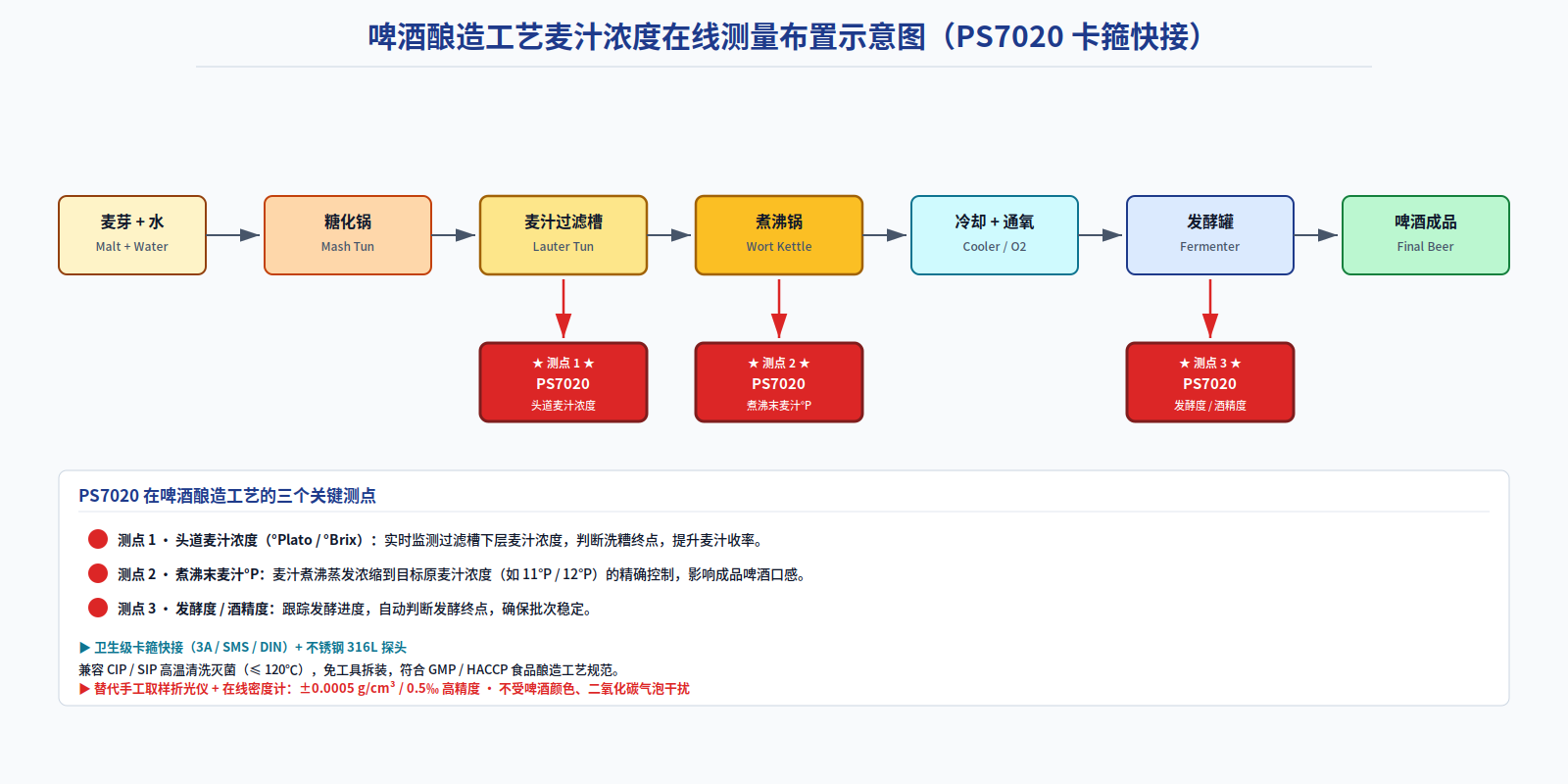
Brewing | Wort concentration and monitoring of fermentation progress |
CIP | Caustic and acid concentration in cleaning solution, and recovery decisions |
Pharmaceutical | Confirmation of make-up concentration and batch-to-batch consistency checks |
Other | |
Crystallisation monitoring | Inline tracking of mother liquor concentration through a crystallisation process |
Phase separation | Rapid detection of a two-phase interface arriving |
Hot melt and polymerisation | Indirect monitoring of reaction progress during polymerisation |
Mounting Arrangements
The three mounting arrangements correspond to three classes of site condition, and the acoustic path length is fixed in all three: spool-piece (flange DN25 / DN50, the mainstream choice for new lines), tri-clamp (quick-release clamp for hygienic processes in food, beverage and pharmaceutical production, with clean-in-place supported) and insertion (insertion flange boss for large-bore lines, retrofits, tanks and troughs; insertion depth does not change the path length).
The measuring section must run full at all times, and an upward vertical run is best. Avoid positions immediately downstream of a pump discharge, a valve or a bend; allow 5D of straight run upstream and 3D downstream. The temperature element is supplied fitted in the measuring spool and must not be relocated to the pipe wall — if it sits away from the acoustic path, the thermal lag during heating and cooling translates directly into drift of the concentration reading.
Technical Specifications
Item | Specification |
Model | PS7020 series (ultrasonic sonic velocity) |
Measuring principle | Ultrasonic time-of-flight (TOF); two sensors in through-transmission, one transmitting and one receiving |
Sensor configuration | 1 × transmitter + 1 × receiver; the acoustic path length is fixed by the measuring spool |
Medium | Solutions and low-solids liquids; free of entrained air, with sonic velocity and concentration corresponding monotonically over the range |
Valid sonic velocity range | 400 to 3500 m/s; outside this range the instrument treats the measurement as invalid and sets a fault bit |
Sonic velocity display resolution | 0.01 m/s |
Concentration range | Established for the medium by calibration on the actual liquid; typically covers 0–100 % within the monotonic section of a binary system |
Primary variable | Mass concentration, volume concentration, density (g/cm³ or kg/m³), degrees Baumé, solids content (g/L); unit selectable |
Diagnostic values | Sonic velocity, sensor temperature, received signal energy, signal quality, fault status word |
Accuracy | Three classes, 0.5 ‰ / 1 ‰ / 5 ‰, corresponding to ±0.0005 / ±0.001 / ±0.005 g/cm³ in density. The classes are functions of the calibration conditions; the prerequisites and the acceptance basis for each are given in 4.4 |
Power supply | AC 220 V (AC 100–240 V, 50/60 Hz wide-range input) or DC 24 V; both are standard |
Ambient temperature | −40 to +80 °C |
Medium temperature | Standard −20 to +80 °C; high-temperature version −20 to +120 °C (to be specified when ordering) |
Working pressure | ≤ 2.0 MPa |
Humidity | 0 to 98 %RH, non-condensing |
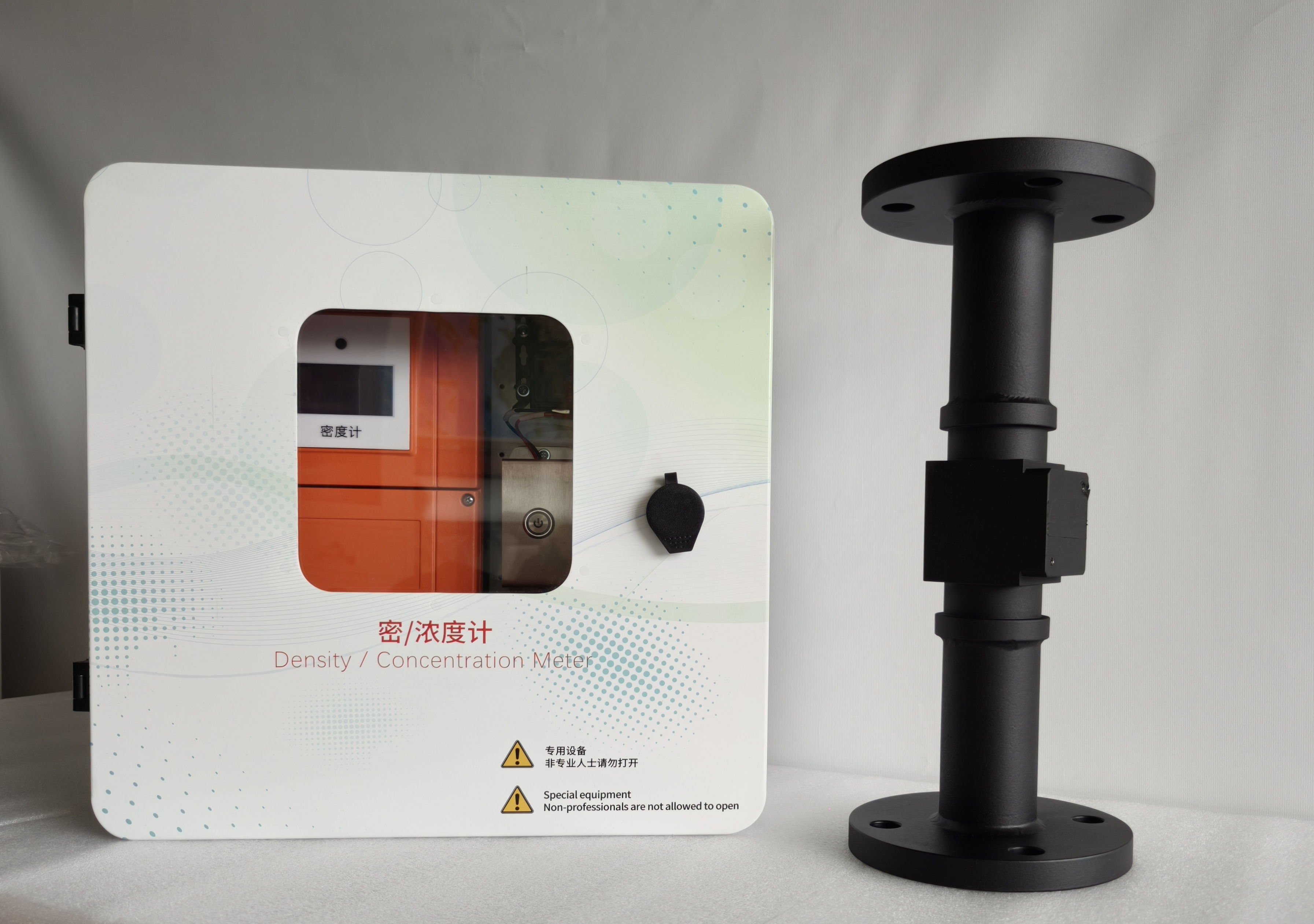
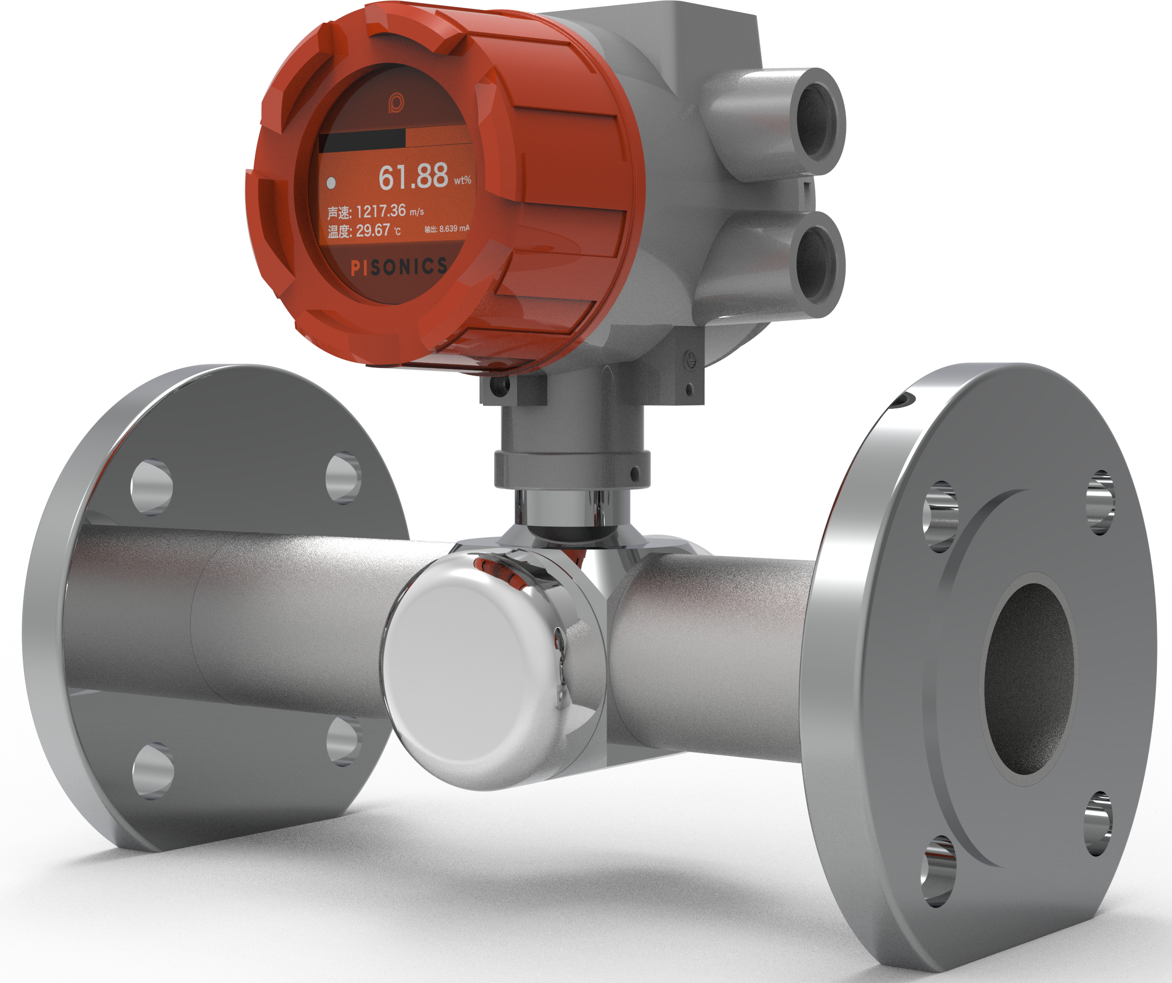
Construction | Integral: measuring spool and transmitter in one body, with readings and configuration available in the field |
Mounting | Spool-piece (flanged) / tri-clamp (quick release) / insertion; see chapter 10 |
Standard bore | Spool-piece DN25 / DN50; other bores confirmed against the order |
Process connection | Flange (DIN / ANSI / JIS), quick-release tri-clamp, insertion flange boss; to be specified when ordering |
Wetted material | 316L stainless steel; other materials confirmed against the duty |
Dimensions and weight | Depend on bore and process connection; as shown on the order drawing |
Temperature sensing | PT1000 sensor temperature (22-bit Σ-Δ acquisition with open-circuit and short-circuit diagnostics) |
Analogue output | 2 × 4–20 mA to NAMUR NE43; the output variable (concentration / temperature / signal energy / sonic velocity), the range endpoints, the correction coefficients and the fault current are set independently for each channel |
Digital communication | RS485 Modbus-RTU, slave address 1–247, baud rate 1200 / 2400 / 4800 / 9600 / 19200 / 38400 / 57600 / 115200 bps (57600 ex works), transmission distance approx. 500 m |
HART | HART 5 slave, Bell 202 FSK (1200 bps) superimposed on 4–20 mA loop 1; primary variable is concentration, secondary variable is sensor temperature |
Bluetooth | Bluetooth 5.4 BLE; live readings and the complete parameter set can be handled from a phone or tablet |
Remote transmission | 4G / DTU connection to the Pisonics cloud platform (option) |
Fieldbus | Profibus-DP (option) |
Display and operation | Local display window, bilingual Chinese/English menu, infrared remote control; remote digital display available as an option |
Factory calibration | 40 independent calibration sets, each with up to 16 concentration points × 15 temperature points, retained in Flash |
Field calibration | Two-point or multi-point linear regression Y = aX + b, up to 20 points; from 3 points onward accepted automatically on r² ≥ 0.8 |
Data storage | 360 records in the instrument (logging interval configurable; 20 min by default, about 5 days). Telemetry is retained for 90 days once connected to the cloud platform |
Firmware update | Dual-slot OTA with CRC-32 whole-image verification and device-type identity check; the existing firmware is retained automatically if an update fails. Remote update from the cloud is supported |
Ingress protection | IP65 |
Hazardous area | Ex d IIC T6 Gb (option, to be specified when ordering) |
Certification | EU CE (certificate supplied with the instrument) |
※ Where the suitability of a medium is hard to judge, please provide a sample and the process data; Pisonics will issue a proposal after an acoustic pre-assessment. The PS7020 Technical Specification is the authoritative source for the complete data and for the prerequisites of each accuracy class.