Measuring Cement Slurry Density Online in Well Cementing: How Do You Cope With High Pressure, Air Entrainment and Weighted Slurries?
Replacing nucleonic and vibrating element density meters with the ultrasonic acoustic-impedance method, providing the closed-loop density input for one-touch automatic mixing on a cementing unit
Scope: well cementing in oil and gas drilling and completion — the continuous mixing return line and the high-pressure manifold of a cementing unit (skid); the same approach extends to density monitoring of spacers and flushes
▍Project Snapshot / Process Conditions
Customer industry | Oil and gas drilling and completion / cementing equipment |
Region | A cementing equipment manufacturing and operating site in south-west China |
Measured medium | Cement slurry (including ultra-low-density lost-circulation and weighted slurries), spacer, flush |
Medium temperature | Ambient temperature duty (the standard instrument allows 0 ~ 80 ℃) |
Pipe size / installation | Cementing unit mixing return / high-pressure manifold line; opposed dual sensors, sensor housings welded to the spool |
Range / accuracy | 1.0 ~ 3.0 g/cm³; ± 1 % |
Field calibration | Put into service directly after clean-water calibration; checked by the gravimetric sampling method |
Replaces | Radioisotope (gamma-ray) density gauges, Coriolis mass flow and density meters, vibrating fork density meters, the manual mud balance |
Operating record | Dedicated verification testing at five densities and three velocities completed; deployed and running at a site in south-west China |
1 Process Background and Measurement Challenges
▍1.1 The density window leaves only 0.02 ~ 0.05 g/cm³ of margin
Cementing is a critical stage of drilling and completion: the cement slurry is pumped into the annulus between the casing and the formation, where it sets to form a cement sheath that isolates the oil, gas and water zones and supports and protects the casing. The density of the slurry must fall precisely inside the "safe density window" between the formation pore pressure and the fracture pressure, and both edges of that window are hard limits:
▪ Density too low: the hydrostatic head in the annulus is insufficient, which readily leads to gas influx and even to a blowout, while the set cement lacks strength and zonal isolation quality is poor;
▪ Density too high: above the formation fracture pressure it causes lost circulation, loss of cement slurry and channelling, and the cementing job is ruined.
In deep and ultra-deep wells, and in high-temperature, high-pressure wells with a narrow pressure window, the margin available for adjusting density is often only 0.02 ~ 0.05 g/cm³. Modern cementing is moreover carried out largely by continuous mixing on a cementing unit (skid), with dry cement and water blended online in proportion and the density fluctuating in real time as mixing proceeds — and "one-touch" mixing, in which the control system adjusts the water-to-cement ratio automatically to a target density, presupposes an online instrument that outputs density in real time, accurately and stably. Once the density measurement is distorted, automatic control is out of the question and operation falls back on manual experience.
A second change is that the range required is widening: ultra-low-density lost-circulation cement slurries and weighted cement slurries are both being used more, and a single instrument has to cover the span from 1.0 ~ 3.0 g/cm³.
▍1.2 Limitations of Existing Measurement Methods
▪ Radioisotope (gamma-ray) density gauges: the accuracy is acceptable, but the built-in radioactive source makes them radiation-based measuring instruments requiring a Radiation Safety Licence. When a cementing unit is moved between regions or works on an offshore platform, the transport, storage and decommissioning and disposal of the source are strictly controlled, and both the purchase price and the annual maintenance cost are high.
▪ Coriolis mass flow and density meters: the mainstream fitment on cementing units at present, but their error is large on low-density cement slurries and on the gas-liquid two-phase medium that mixing produces, which makes them difficult to rely on for remote automatic control; build-up forms readily on the inner wall of the slightly bent measuring tube, and once it does the whole instrument fails, with high costs for spares, inspection and repair.
▪ Vibrating fork / vibrating element density meters: two shortcomings compound each other. First, the maximum working pressure is usually of the order of 10 ~ 20 MPa, which is difficult to reconcile with the high-pressure manifold of cement pumping; second, the calibration range of such instruments mostly stops at around 1.8 g/cm³, whereas a conventional neat cement slurry is already above 1.87 g/cm³ and a weighted slurry exceeds 2.2 g/cm³, so the main working area of cementing lies outside their calibrated range altogether.
▪ Differential pressure density meters and the manual mud balance: the former is affected by the structure of the cementing unit and by the slurry surging up and down as it is agitated during mixing, so the reading drifts, and diaphragm life is short in a high-pressure, severely abrasive duty; the latter depends on manual sampling at intervals, so the data lag and are discrete and cannot take part in closed-loop control.
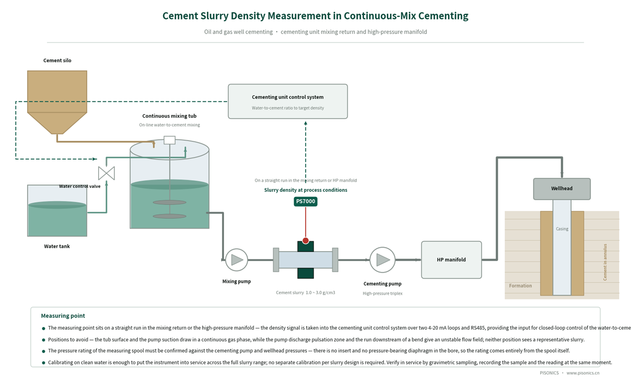
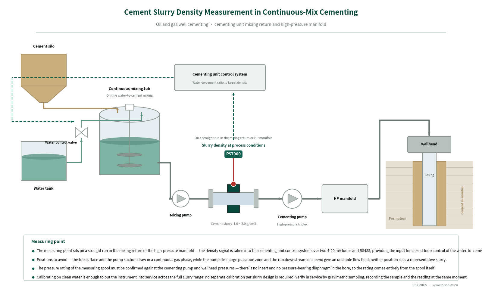
Figure 1 Schematic process layout for online cement slurry density measurement in continuous cementing mixing
2 The PS7000 Technical Approach
▍2.1 Measuring principle: the chirped (linear frequency modulation) acoustic-impedance method
When an ultrasonic wave travelling in a medium meets a solid-liquid interface, the echo amplitude is determined by the difference in acoustic impedance across that interface, and acoustic impedance Z = medium density ρ × sound velocity c is directly related to the density of the medium. The instrument continuously emits chirped (linear frequency modulated) ultrasonic pulses and acquires the echoes in real time, and the transmitter analyses the acoustic impedance signature of the echo by algorithm to recover the density of the medium.
The broadband character of the chirp signal helps it penetrate a bubble layer and suppress multiple-reflection interference — which matters particularly in cementing mixing duty: continuous mixing is itself a strongly air-entraining process, and a vibrating element instrument counts the bubbles that enter its measuring tube directly as low-density medium, a deviation that lies in the measuring principle and cannot be corrected by calibration.
The fundamental difference from the gamma-ray method is that the instrument contains no radioactive source of any kind. It is a non-nuclear instrument: no radiation safety licence is required, and there is no annual source inspection, no radiation-worker qualification and no source decommissioning and disposal. Cementing units moving between regions and work on offshore platforms benefit from this in particular.
▍2.2 A construction specific to cementing: welded opposed dual sensors that do not touch the cement slurry
The cementing version is installed differently from the other Pisonics PS7000 models, so it is described separately here:
▪ Welded opposed dual sensors: a flat is machined on each of the opposite sides of the measuring spool, the sensor housings are welded to the spool as one piece, the transducers are encapsulated inside the housings, and two leads run from them to the transmitter.
▪ The sensors do not touch the cement slurry: the transducers work through the pipe wall, and the cement slurry contacts only the inner wall of the spool. This differs from the wetted-sensor installation of the other Pisonics PS7000 models — this construction was chosen for cementing duty precisely in order to deal with high-pressure containment and severe abrasion at the same time.
▪ The pipe wall is the pressure boundary: there is no insert of any kind in the flow path and no pressure-bearing diaphragm, and the maximum working pressure is customised to the pressure rating of the measuring spool, which can be specified to the actual cement pump and wellhead pressure requirements.
▪ No source of build-up or blockage: the flow path is a length of smooth straight pipe, so there is no vibrating tube wall to be eroded by cement and barite, and no whole-instrument failure caused by build-up inside a slightly bent tube.
▪ Limits of applicability: bubbles in the medium are permitted, but the medium should not contain large quantities of suspended or settled coarse particles.
▍2.3 Key Technical Specifications
Item | Specification | Item | Specification |
Measuring principle | Chirped ultrasonic acoustic-impedance method | Pipe diameter | Customised to the bore of the cementing manifold |
Measuring range | 1.0 ~ 3.0 g/cm³ | Installation | Opposed dual sensors, sensor housings welded to the spool |
Accuracy | ± 1 % | Maximum working pressure | Customised to the pressure rating of the measuring spool |
Power supply | DC 24V | Dimensions | 288 (W) × 190 (D) × 95 (H) mm |
Power consumption | 1 W | Weight | Approx. 2.5 kg |
Ambient temperature | -30 ℃ ~ 60 ℃ | Display | OLED screen |
Medium temperature | 0 ℃ ~ 80 ℃ | Analogue output | Dual 4-20 mA |
Humidity range | ≤ 98 %RH | Digital output | RS485 / Profibus DP / Bluetooth 5.2 |
Ingress protection | IP67 | Field calibration | Put into service directly after clean-water calibration, checked by the gravimetric sampling method |
※ The above specifications apply to the high-pressure cementing version and differ from those of the other Pisonics PS7000 models (wetted-sensor installation). The maximum working pressure depends on the pressure rating of the measuring spool and must be confirmed at the selection stage against the cement pump pressure and the wellhead pressure.
▍2.4 Selection and Installation Requirements (important)
The following conditions directly determine the stability of the measurement in the field. We recommend confirming them while the measuring point is still being designed; doing so avoids the great majority of post-commissioning disputes over deviation.
▪ Install on a straight run of the mixing return line or the high-pressure manifold: keep clear of the pulsating section at the pump outlet and of the region downstream of a bend; both ends of the measuring spool are supplied with flanged or welded connections to the pressure rating of the process line.
▪ The reading does not vary with flow velocity, but pronounced two-phase stratified regions must still be avoided: measurements have covered three velocities, 3 / 9 / 15 m/s, with consistent readings; what does have to be avoided are positions where a continuous gas phase enters, such as near the liquid surface in the mixing tub or the vacuum zone at the suction inlet.
▪ The instrument can be put into service after calibration on clean water: a single field calibration on clean water is enough for it to measure cement slurry directly, and there is no need to calibrate separately for each slurry density. This is where the acoustic-impedance method proves its practical value in a duty such as cementing, with its wide density span and rapidly changing formulations.
▪ Moving between regions requires no radiation approval: as a non-nuclear instrument it involves no transport, storage or decommissioning formalities for a radioactive source when the cementing unit is relocated or mobilised to and from an offshore platform.
▪ Media above 80 ℃ must be confirmed separately: the medium temperature limit of the standard version is 80 ℃, and the suitability for high-temperature cementing fluids must be confirmed with Pisonics at the selection stage.
▪ The pressure rating of the measuring spool must be set by the pump pressure: the instrument itself has no pressure-bearing diaphragm, so the maximum working pressure depends entirely on the measuring spool — this has to be confirmed at the selection stage against the actual cement pump and wellhead pressure requirements, and a spool configuration intended for atmospheric duty should not simply be carried over.
▪ Check the range first where one instrument serves both weighted and ultra-low-density slurries: the range is 1.0 ~ 3.0 g/cm³, covering everything from lightweight lost-circulation slurries to weighted slurries; if the site has special formulations outside that band, tell us in advance so that they can be checked.
▍2.5 Field calibration: clean-water calibration plus a check by the gravimetric sampling method
Calibration in cementing service differs from a conventional slurry measuring point: a single calibration on clean water is enough to put the instrument straight into service on cement slurry, with no separate calibration for each slurry density. In the verification test, one instrument calibrated on clean water went on to measure five slurry densities directly, and the readings agreed with the gravimetric reference.
Checks after commissioning still use the gravimetric sampling method: the sampling point should be as close as possible to the measuring spool, and the sample and the reading must be recorded at the same moment — density changes quickly during mixing, and a sampling lag will be mistaken for instrument deviation.
The comparison should be repeated after the measuring spool is changed, the bore is altered or the formulation system is adjusted.
3 Before / After Comparison
Aspect | Original nucleonic / Coriolis / vibrating fork solution | PS7000 solution |
Compliance and relocation | The radioactive source requires a licence, annual inspection and decommissioning and disposal; relocation between regions and offshore work are subject to controls | Non-nuclear and radiation-free; relocation and mobilisation to and from site involve no radioactive source formalities |
Air-entraining duty | Large error in gas-liquid two-phase flow; a vibrating element instrument counts the bubbles entering its measuring tube as low-density medium | Broadband chirp analysis penetrates the bubble layer; positions where a large continuous gas phase enters must still be avoided when siting the point as set out in section 2.4 |
Suitability for high pressure | Vibrating fork instruments commonly have an upper limit of the order of 10 ~ 20 MPa | No inserts and no pressure-bearing diaphragm in the flow path; the maximum working pressure is customised to the pressure rating of the measuring spool |
Range for weighted slurries | The calibration range of vibrating element instruments mostly stops at around 1.8 g/cm³ | 1.0 ~ 3.0 g/cm³, verified by measurement at 2.48 g/cm³ |
Build-up and maintenance | Build-up in the slightly bent tube disables the whole instrument, with high costs for spares, inspection and repair | The flow path is a smooth straight pipe, with no source of build-up or blockage |
Calibration workload | A change of slurry formulation usually calls for recalibration | After clean-water calibration it can be used directly on cement slurry, with no calibration point by point |
4 Field Verification and Operating Record
The solution has completed a round of dedicated verification testing: five cement slurries at 1.28 / 1.59 / 1.90 / 2.28 / 2.48 g/cm³ were measured continuously at three flow velocities of 3 / 9 / 15 m/s and compared against the manual gravimetric method point by point. One instrument was calibrated on clean water and then put straight into service, with no separate calibration at the individual density points.
Result: at every density point the deviation between the instrument reading and the gravimetric reference was within ± 0.03 g/cm³, and at any one density point the readings at the three velocities agreed — and the two findings mean different things for cementing. The first shows that the range remains usable up into the weighted slurry band; the second shows that the reading does not vary with the mixing flow rate, so what the DCS receives is density itself and not a function of flow.
The solution has been deployed on the mixing line of a cementing truck at a cementing equipment manufacturing and operating site in south-west China, has been compared repeatedly against manual sampling and laboratory values, and has run stably over a long period. A high-pressure wellhead version for high-pressure offshore cementing is in prototype development.
A Note on Comparison Methodology Field comparison carries a methodological error of its own: the distance between the sampling point and the measuring point introduces a transport lag, and the representativeness of the sampling operation and the precision of the laboratory step both contribute deviation. We therefore avoid expressions such as "in complete agreement" and recommend instead that acceptance be based on the average deviation and trend agreement across several consecutive comparisons, with the sampling rules specified in an annex to the contract. Pisonics can supply a standard field comparison and acceptance procedure. |
▍Verifiable Benefits for the Customer
▪ Licensing, annual inspection, personnel qualification and decommissioning and disposal of a radioactive source are all avoided, so moving a cementing unit between regions and mobilising to and from offshore platforms are no longer constrained by radiation source controls.
▪ After calibration on clean water the instrument can be used on cement slurries of any density, with no need to calibrate for each formulation, which shortens the preparation time before a job.
▪ There are no inserts and no pressure-bearing diaphragm in the flow path, which does away with the cleaning and replacement work needed after build-up in a slightly bent tube.
▪ The density signal is taken into the cementing truck control system over dual 4-20 mA outputs and RS485, providing a usable input for closed-loop control of the water-to-cement ratio.
5 Frequently Asked Questions
Q1 Can it still measure a weighted slurry above 2.4 g/cm³?
A The range is 1.0 ~ 3.0 g/cm³, and the highest density point in the verification testing was 2.48 g/cm³, where the reading agreed with the gravimetric reference. This point deserves a note of its own: the calibration range of many vibrating element instruments stops at around 1.8 g/cm³, whereas a conventional neat cement slurry is already above 1.87 g/cm³ and a weighted slurry exceeds 2.2 g/cm³ — when selecting an instrument, ask directly for a calibration certificate covering the 1.9 ~ 2.4 g/cm³ band rather than looking only at the nominal accuracy figure. If a formulation on site goes beyond 3.0 g/cm³, tell us in advance so that it can be checked.
Q2 Mixing entrains a great deal of air — will bubbles pull the reading off?
A The broadband chirp signal penetrates the dispersed bubbles entrained during mixing reasonably well, and this is precisely where the acoustic-impedance method differs in principle from the vibrating element method — a vibrating element instrument measures the total mass inside its tube, so bubbles entering the measuring tube are counted as low-density medium, a deviation that lies in the measuring principle and cannot be corrected by calibration. The limits should be stated as well: where there is a continuous gas phase at the measuring point — near the liquid surface in the mixing tub, or in the vacuum zone at the suction inlet — no acoustic method can read a representative slurry, and the correct response is to move the measuring point on the principles set out in section 2.4.
Q3 Does the reading vary with the mixing flow rate?
A The verification testing addressed this specifically: at any one density point the readings at the three velocities of 3 / 9 / 15 m/s agreed. That matters in practice for cementing — the rate during continuous mixing varies in itself, and if the reading drifted with velocity what the DCS received would be a mixture of density and flow, and the closed loop would be pulled off target. Note that the measuring point should still keep clear of the pulsating section at the pump outlet and of the region downstream of a bend; the problem there is not the velocity but the unstable flow field.
Q4 Do the sensors touch the cement slurry? Is this the same as your other models?
A The cementing version does not touch it. The transducers are encapsulated in sensor housings welded to the spool as one piece and work through the pipe wall, so the cement slurry contacts only the inner wall of the spool. This differs from the other Pisonics PS7000 models, which have a wetted-sensor installation with the sensor face flush with the inner wall of the pipe. Welded opposed dual sensors were chosen for cementing duty in order to deal with high-pressure containment and severe abrasion at the same time: there is no insert and no pressure-bearing diaphragm in the flow path, and the maximum working pressure is determined by the pressure rating of the measuring spool.
Q5 How is it calibrated in the field? Does it have to be recalibrated for every change of slurry?
A No. A single field calibration on clean water is enough for the instrument to be put straight to work on cement slurry. In the verification testing one and the same instrument, calibrated on clean water, measured cement slurries at five densities in succession — 1.28 / 1.59 / 1.90 / 2.28 / 2.48 g/cm³ — with readings consistent with the gravimetric reference. Checks after commissioning use the gravimetric sampling method, with the sampling point as close as possible to the measuring spool and the sample and the reading recorded at the same moment: density changes quickly during mixing, and a sampling lag is easily mistaken for instrument deviation.
Q6 Should the PS7000 or another model be selected for a given measuring point?
A For a high-pressure, severely abrasive, gas-bearing medium such as cement slurry, the PS7000 cementing version is the corresponding choice in the Pisonics range. For other duties: for slurry density at atmospheric pressure choose the PS7000 standard version (wetted-sensor installation); where the pipe cannot be tapped, or an ageing line is being retrofitted, choose the PS7010 clamp-on; for concentration analysis on clean liquids choose the PS7020 (sound velocity); for multi-component concentration analysis choose the PS7100 (optical spectral); for a binary system in a coloured or turbid medium choose the PS7110 (refractometry); for large tanks and large bores with low-abrasion liquids choose the PS7300 (differential pressure); for clean chemical liquids needing a high resolution choose the PS7400 (vibrating fork); for aqueous suspensions choose the PS7600 (microwave).
About Pisonics
Xi'an Pisonics Information Technology Co., Ltd. (PISONICS) specialises in industrial online density and concentration measurement. Its product range covers ultrasonic acoustic impedance, ultrasonic sound velocity, clamp-on acoustic attenuation, spectral, refractometric, vibrating fork, differential pressure, Coriolis and microwave measuring principles, so that a suitable solution can be matched to each duty, and it is in service in the chemical, petrochemical, power, metallurgical, pharmaceutical, food and municipal industries.
Inline Density & Concentration Measurement
Company | Xi'an Pisonics Information Technology Co., Ltd.PISONICS |
Address | Room 15B016, Block A, Olympic Building, North Chang'an Road, Beilin District, Xi'an, Shaanxi, China |
Tel | +86 159-0293-2017 |
info@pisonics.com | |
Web | Chinese site www.pisonics.cn | English site www.pisonics.com |
※ The process data and operating records in this case are compiled from an actual project; Figure 1 is a process layout diagram, not a measured record trace. Instrument specifications and the installation and calibration requirements are governed by the technical documentation supplied with the goods, and are subject to change without notice.