Online Concentration Measurement of Hydrometallurgical Leach Solutions: Selection Limits for Hot, Strongly Acidic Duty
Ultrasonic acoustic-impedance measurement replaces gamma gauges, differential pressure meters and manual sampling — continuous concentration monitoring of leach solution, raffinate and electrowinning catholyte
Scope: copper / cobalt / nickel / lithium hydrometallurgical L-SX-EW circuits — three classes of measuring point: the leach reactor outlet, the SX raffinate line and the electrowinning catholyte circulation line
▍Project Snapshot / Process Conditions
Customer industry | Hydrometallurgy / non-ferrous metals refining |
Region | A large overseas copper hydrometallurgy project |
Measured medium | PLS leach solution / raffinate / electrowinning catholyte (Cu²⁺ + H₂SO₄) |
Medium temperature | Varies widely between points; the hot leaching stage exceeds the 0 ~ 80 ℃ limit of the standard version and requires a high-temperature custom version, with the specific upper limit confirmed with Pisonics during selection |
Pipe size / installation | DN80 ~ DN150; measuring spool flanged into a straight run, non-intrusive sensor, lining and wetted materials customised against a full solution analysis |
Range / accuracy | 0 ~ 80 % concentration by weight, ± 1 % FS (the datasheet figure is stated as ± 1 % concentration by weight); the three points cover different concentration ranges and should each be calibrated on their own medium |
Field calibration | Gravimetric sampling method, or comparison against plant laboratory values; calibrated online, no shutdown required |
Replaces | Gamma (nuclear) concentration gauge, differential pressure density meter, manual sampling and analysis |
Operating record | Project feedback: one year in service, all three points running continuously, with the variation band of electrowinning catholyte concentration narrowed |
1 Process Background and Measurement Challenges
▍1.1 Solution concentration is the shared control variable across all three L-SX-EW stages
Hydrometallurgy is the mainstream route for refining copper, cobalt, nickel, lithium and uranium. The typical circuit is leaching — solvent extraction — electrowinning, abbreviated L-SX-EW: the target metal in the ore is first taken into solution by acid leaching to form pregnant leach solution (PLS); an organic phase then extracts it selectively and, after stripping, forms a concentrated electrolyte; finally the metal is electrodeposited in the cell house on stainless steel cathodes against lead-silver anodes to produce cathode metal.
The three stages have different operating variables, but their control targets all come back to solution concentration:
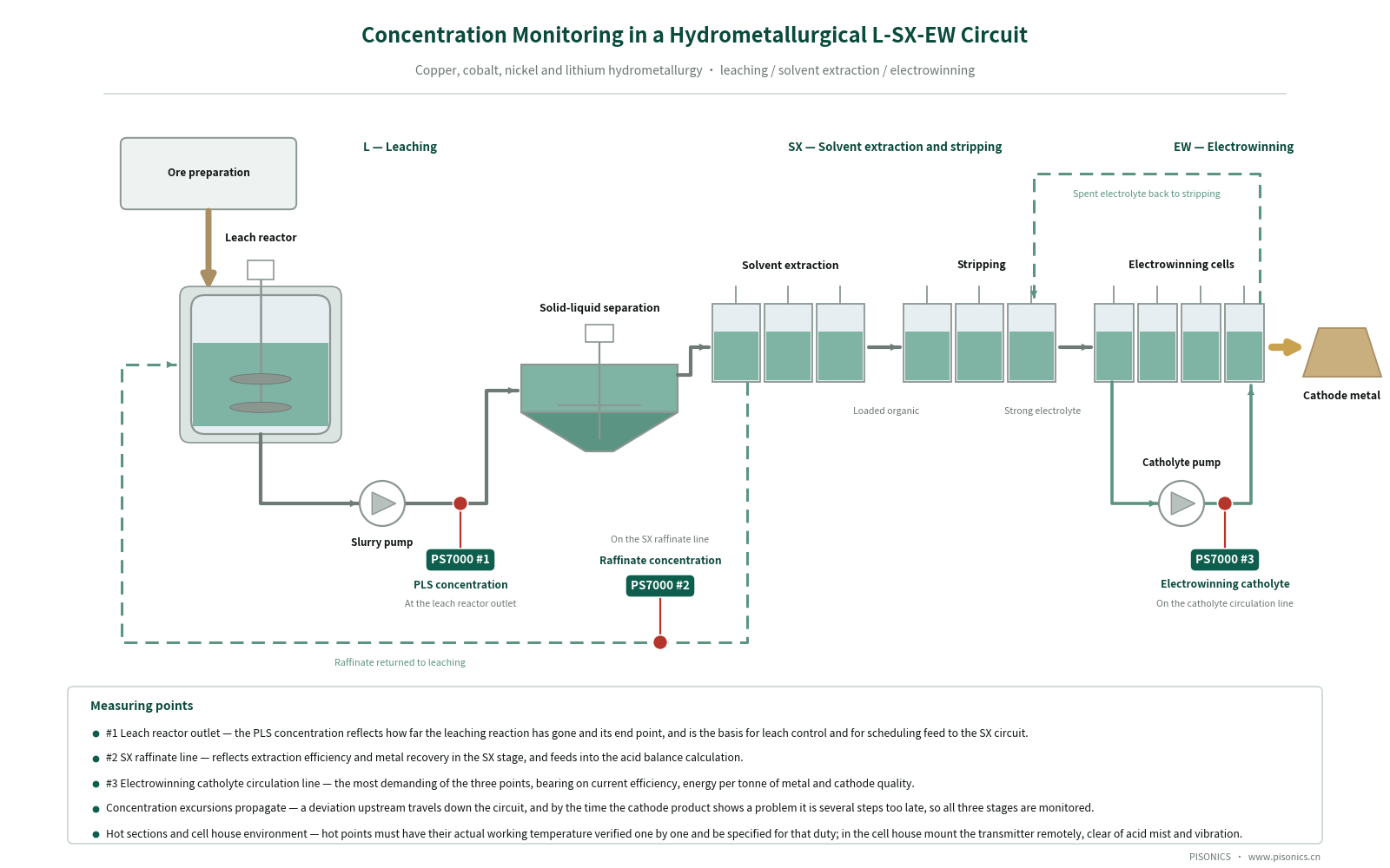
▪PLS concentration — reflects the progress and end point of the leaching reaction and is the basis for leach control and for scheduling feed to the SX system;
▪Raffinate concentration — reflects extraction efficiency and metal recovery in the SX stage, and is also used in the acid balance calculation;
▪Cu²⁺ / H₂SO₄ concentration in the electrowinning catholyte — bears directly on current efficiency, energy consumption per tonne of metal and cathode quality, and is the most demanding of the three measuring points;
▪Concentration excursions propagate — a deviation upstream travels down the circuit, and by the time the cathode product shows a problem it is several process steps too late.
Hydrometallurgical mine sites are mostly in remote regions — South America, Africa, Qinghai — with limited laboratory resources and staffing, so manual sampling and analysis is usually done once a shift or even once a day. On projects like these a continuous online concentration trend is often worth more than higher single-point accuracy — provided the instrument can survive long term in a hot, strongly acidic environment and does not add a compliance burden on site.
▍1.2 Limitations of Existing Measurement Methods
▪Gamma (nuclear) concentration gauge: it handles strongly corrosive media, but it is a radiation-based measuring device. Customs clearance for importing the source, licensing, annual inspection and source decommissioning and disposal are often impractical at a remote mine site; the safety and ESG compliance reviews of multinational mining companies also tend to be reserved about radioactive sources, and the approval timeline cannot be controlled.
▪Differential pressure / diaphragm density meter: the impulse lines and diaphragms are in direct contact with a combined corrosive medium of concentrated acid + high metal ion content + Cl⁻ / F⁻. If a diaphragm perforates, the leaked fill fluid enters the solution and may trigger knock-on losses such as poisoning of the SX organic phase or nodulation of electrowinning cathodes, at a cost far exceeding that of the instrument. Impulse lines are also prone to crystallisation and blockage in hot, strongly acidic service.
▪Manual sampling and analysis: performed once a shift or even once a day, it cannot keep up with changes in the leaching and electrowinning circuits; sampling hot, strongly acidic solution on site is itself an occupational safety risk.
▪Combined interference in the cell house: strong electromagnetic fields, acid mist and vibration superimposed on one another place heavy demands on interference rejection, enclosure protection and wiring practice, and ordinary instruments readily show output drift in the EW section.
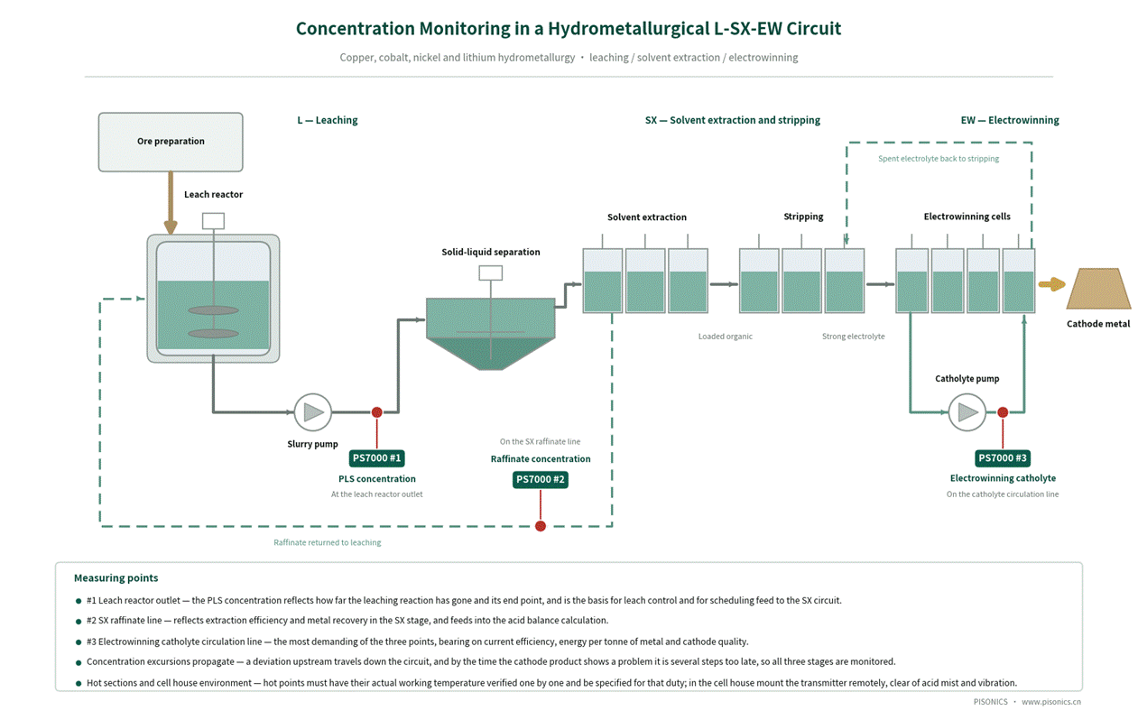
Figure 1 Layout for online concentration monitoring across a hydrometallurgical L-SX-EW circuit (PS7000 #1 PLS / #2 raffinate / #3 electrowinning catholyte)
2 The PS7000 Technical Approach
▍2.1 Measuring principle: the chirped (linear frequency modulation) acoustic-impedance method
When an ultrasonic wave travelling in a medium meets a solid-liquid interface, the echo amplitude is determined by the difference in acoustic impedance across that interface, and acoustic impedance Z = medium density ρ × sound velocity c is directly related to the density of the medium. The PS7000 uses a single self-transmitting, self-receiving sensor that continuously emits chirped (linear frequency modulation) ultrasonic pulses and acquires the echoes in real time. The wide bandwidth of the chirp signal helps the pulse penetrate bubble layers and suppresses multiple-reflection interference, and the transmitter then resolves the acoustic-impedance signature of the echo to recover the density of the medium.
The fundamental difference from the gamma-ray method is that the PS7000 contains no radioactive source of any kind. It is a non-nuclear instrument: no radiation safety licence is required, and there is no annual source inspection, no radiation-worker qualification and no source decommissioning and disposal.
▍2.2 Non-intrusive measurement: the sensor is wetted but does not protrude into the flow path
The PS7000 measuring spool is flanged into a straight run of the process line and the ultrasonic sensor is mounted on the spool. This is the key structural difference from conventional insertion-type instruments, and the point most often misunderstood during selection, so it is set out here exactly as it is worded in the Operating Manual:
▪Non-intrusive (non-intrusive is not the same as non-contact): the sensor must be wetted by the medium in order to work, but it does not protrude into the flow path — there is nothing projecting into the bore. The manual is explicit on this point: for horizontal installation with the sensor on top of the pipe, a full pipe must be guaranteed, otherwise the sensor loses contact with the liquid and the measurement fails; for remote-mount horizontal installation the sensor should be placed on the underside of the pipe so that it stays wetted.
▪There is therefore none of the leading-edge erosion, build-up at the probe root or downstream flow disturbance associated with insertion probes, and no risk of blocking the line.
▪The acoustic window of the sensor is sapphire: a fine surface finish, wear-resistant and corrosion-resistant. The measuring spool can be supplied with a lining (PTFE / rubber / ceramic) to suit the duty.
▪Heavily scaling media should still be included in routine inspection — the manual lists "scaling on the sensor face" as one of the items to check when calibration fails, the remedy being to clean the sensor and recalibrate.
▪Applicability limits: bubbles in the medium are permitted; the medium should not, however, contain large quantities of suspended or settled coarse particles.
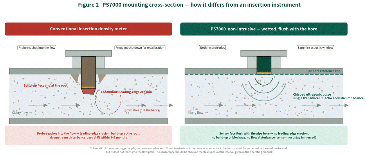
Figure 2 Sectional view of the PS7000 installation — the structural difference from conventional insertion types (schematic drawing of the principle, not a record of measured data)
▍2.3 Key Technical Specifications
Item | Specification | Item | Specification |
Measuring principle | Chirped ultrasonic acoustic-impedance method | Pipe diameter | DN50 ~ DN1000 |
Measuring range | 0 ~ 80 % concentration by weight / calibratable on the actual medium | Installation | Integral / remote-mount, flanged into a straight run |
Accuracy | ± 1 % FS (the published datasheet figure is ± 1 % concentration by weight) | Dimensions | 288 (W) × 190 (D) × 95 (H) mm |
Power supply | Standard AC220V (175 ~ 285V, 50/60Hz); DC24V optional | Weight | Approx. 2.5 kg |
Power consumption | ≤ 1 W | Display | OLED screen (bilingual Chinese / English menu) |
Ambient temperature | -30 ℃ ~ 60 ℃ | Analogue output | 4-20 mA, 2 channels |
Medium temperature | 0 ℃ ~ 80 ℃ | Digital interface | RS485 / Modbus RTU, approx. 500 m |
Humidity range | ≤ 98 %RH | Ingress protection | IP65 |
Data storage | 2000 real-time records + 400 daily records (customisable) | Remote transmission | Optional 4G module |
Field calibration | Gravimetric sampling method, performed online with no shutdown | Custom options | Lining, range, explosion protection, high temperature and similar options built to the duty |
※ At some of these measuring points the medium temperature exceeds the 0 ~ 80 ℃ range of the standard version, so a high-temperature custom version must be selected; the specific upper limit is to be confirmed with Pisonics during selection, and no high-temperature limit is quoted in this document. The spool lining, sensor material, flanges and seals are custom items, to be confirmed item by item against a full solution analysis (Cu²⁺, H₂SO₄, Cl⁻ / F⁻, entrained organic phase, temperature).
▍2.4 Selection and Installation Requirements (important)
The following conditions directly determine the stability of the measurement in the field. We recommend confirming them while the measuring point is still being designed; doing so avoids the great majority of post-commissioning disputes over deviation.
▪Vertical installation with upward flow is preferred. For horizontal installation, confirm that the medium is not stratified and that the measuring point is representative.
▪Flow velocity > 1 m/s; the higher the density of the solid phase, the higher the velocity required. Avoid low-velocity or stagnant duties, in which particle settling disturbs accuracy and stability.
▪Straight run requirement: the installation position should be well clear of pumps, valves, bends and other local resistances; for horizontal installation, 10D upstream / 5D downstream of straight run must be provided (5D upstream / 3D downstream as an absolute minimum).
▪Keep the sensor wetted: for integral horizontal installation with the sensor on top of the pipe, the pipe must run full; for remote-mount horizontal installation the sensor should be placed on the underside of the pipe. Where the pipe does not run full, the remote-mount version is preferred.
▪Avoid points where free gas bubbles accumulate. Aeration, twin-pump suction, negative-pressure inlets and similar conditions introduce large quantities of free gas bubbles; the bubbles raise the echo energy and bias the reading high. This is an inherent limitation of the acoustic method and must be handled by the choice of measuring point, not by compensating in calibration.
▪The comparison sampling point should be as close as possible to the measuring point. A sampling point far from the measuring point introduces transport lag, so the laboratory reference value and the displayed reading no longer refer to the same moment, and the difference is easily mistaken for instrument error.
▪High-temperature points must use the custom version, and temperature must be verified point by point: the medium temperature range of the standard version is 0 ~ 80 ℃, and this is a hard limit — above it a high-temperature custom version is mandatory. The upper limit of the high-temperature version falls within the custom range and is to be confirmed with Pisonics during selection, with the actual maximum working temperature, normal temperature and range of variation supplied for each individual point rather than one blanket temperature band for the whole plant. Note too that the ambient temperature rating of the transmitter is -30 ~ 60 ℃ — radiated heat near a hot line will push the transmitter environment beyond that, so such points should use the remote-mount version with the transmitter moved to a well-ventilated position.
▪Wetted materials must be confirmed against a full solution analysis: in a combined corrosive environment of concentrated acid plus Cl⁻ / F⁻, the spool lining, sensor material, flange sealing faces and seals all need checking item by item, and any organic phase entrainment in the SX section should be declared at the same time. Corrosion failures on site occur mostly at the seals and flange faces rather than in the lining itself; we recommend writing the material list into the technical agreement.
▍2.5 Field calibration: the gravimetric sampling method, performed online
Calibration brings the displayed value into agreement with the true density of the medium: several pairs of "instrument reading + corresponding laboratory reference value" are collected and the instrument automatically regresses the correction coefficients. The whole procedure requires no shutdown and can be carried out online provided the process is steady and the sensor is clean.
Process conditions to be confirmed, item by item, before calibration:
Full pipe | The sensor must be completely immersed in the liquid |
Steady flow | Variation within ± 5 % |
No significant bubbles | No venting operation should be in progress in the line |
Steady temperature | A change in slurry temperature affects the measurement signal |
Clean sensor | No significant deposit or scaling; rinse with clean water if necessary |
The most common situation in the field is that only the process medium is available and clean water cannot be introduced temporarily. In that case two consecutive acquisitions are made on the same medium (about 2 minutes each, about 4 minutes in total): the two measured points plus the virtual zero point added automatically by the system form three regression points, and the instrument uses the goodness of fit r² to cross-check the consistency of the two signals. If bubbles, a step change in flow or an abnormal valve movement during acquisition make the two data sets inconsistent, the system rejects the calibration outright rather than returning an incorrect coefficient. This is the key mechanism that prevents a calibration that looks successful but is in fact wrong.
Recommended calibration interval: calibrate a newly installed instrument once within the first 12 ~ 24 hours of operation; once operation is stable, verify every 6 ~ 12 months; verify every 1 ~ 3 months at measuring points with demanding accuracy requirements; recalibrate immediately after changing the sensor or the medium.
3 Before / After Comparison
Aspect | Previous gamma / differential pressure + manual sampling solution | PS7000 solution |
Compliance and cross-border deployment | A radioactive source brings customs clearance, licensing, annual inspection and decommissioning; hard to implement at remote mine sites, and constrained by ESG and safety review | Non-nuclear and radiation-free, with no radiation approvals or source management; overseas deployment is not bound by radioactive source management procedures |
Corrosion resistance and contamination risk | The diaphragm is directly wetted and pressure-bearing; after perforation the leaked fluid enters the solution and may poison the SX organic phase or cause nodulation in electrowinning | Only the spool bore and the sensor face are wetted; no protrusions and no pressure-bearing diaphragm in the flow path; lining and wetted materials customised against a full solution analysis |
Data continuity | Analysis is carried out once a shift or once a day, so changes in concentration are recognised well after the event | Continuous online output, usable as the trend basis for leach end-point assessment, extraction efficiency calculation and electrowinning acid make-up |
High-temperature capability | The impulse lines of a differential pressure transmitter are prone to crystallisation and blockage in hot, strongly acidic service, requiring frequent maintenance | Hot measuring points require a high-temperature custom version; the standard version is limited to 0 ~ 80 ℃ and the upper limit of the high-temperature version is confirmed during selection |
Measurement performance | — | ± 1 % FS (the published datasheet figure is ± 1 % concentration by weight) over the full 0 ~ 80 % range, calibratable on the actual medium |
System integration | Single analogue output, or manual entry into a logbook | 4-20 mA × 2 + MODBUS-RTU, optional 4G, supporting central monitoring and remote diagnostics |
4 Field Verification and Operating Record
On a large overseas copper hydrometallurgy project, three PS7000 units were installed at the leach reactor outlet (PLS), on the SX raffinate line and on the electrowinning catholyte circulation line. Project feedback: all three points ran continuously through the first year of service; the variation band of Cu²⁺ concentration in the electrowinning catholyte narrowed from about ± 3 g/L to about ± 0.8 g/L, and current efficiency over the same period was recorded as improving by around 1.5 percentage points.
The figures above are the project's own operating feedback, compiled to its own statistical conventions. It should be noted that current efficiency is affected by current density, cell temperature, additives, electrode management and short-circuit rate among other factors, and the 1.5 percentage point change should not be attributed to a single instrument. A more accurate statement is this: once concentration was available as a continuous online value, acid make-up and feed adjustment had something to work from, and that is one of the conditions behind the improvement in current efficiency. For acceptance we recommend taking the plant's own laboratory values as the reference, collecting several consecutive sets of "meter reading + laboratory value from a sample taken at the same moment", and judging on average deviation and trend agreement, with the sampling point, sampling timing and analytical method specified in an annex to the contract.
Comparable solutions have since been used on cobalt hydrometallurgical refining, nickel laterite pressure leaching and salt-lake lithium extraction projects in China. It should be noted that these applications differ widely in temperature, acidity, halide content and organic phase system, so selection cannot simply be copied from this case and must be calculated individually against each full solution analysis and its temperature conditions.
A Note on Comparison Methodology The gravimetric sampling method itself carries method error: the physical distance between the sampling point and the measuring point introduces transport lag, and the representativeness of the sampling operation together with the weighing and drying accuracy in the laboratory also contribute to the deviation. We therefore avoid expressions such as "in complete agreement", and recommend instead that acceptance be based on the mean deviation and the trend consistency across several consecutive comparison sets, with the sampling rules stated explicitly in an annex to the contract. Pisonics can provide a standard field comparison and acceptance procedure. |
▍Verifiable Benefits for the Customer
▪No customs clearance for importing a source, no licensing, no annual inspection, no radiation worker qualification and no source decommissioning and disposal, which simplifies the compliance route for remote mine sites and cross-border projects.
▪The design removes the pressure-bearing diaphragm as a leak path, lowering the risk that an instrument failure triggers knock-on losses such as contamination of the SX organic phase or nodulation of electrowinning cathodes.
▪All three points use the same instrument model, so spares and maintenance are common; calibration is completed online by the gravimetric sampling method, with no shutdown required.
▪With the concentration signals in the central monitoring and remote diagnostic platform, leach end-point assessment, extraction efficiency calculation and electrowinning acid make-up all have a continuous input to work from (the actual process improvement is per the plant's own operating statistics).
5 Frequently Asked Questions
Q1 Our process runs above 80 ℃, so is the standard version ruled out? How high can the high-temperature version actually go?
A Yes, the standard version is ruled out — the medium temperature range given in the manual is 0 ~ 80 ℃ and this is a hard limit; above it a high-temperature custom version is mandatory. The upper limit of the high-temperature version falls within the custom range and has to be confirmed after calculation against the maximum working temperature, the amplitude of variation, the pipe material and the insulation at the specific point. We do not quote a single blanket figure in case material, so please provide the actual temperature of each point individually during selection. Two further items are often overlooked. First, the ambient temperature rating of the transmitter is -30 ~ 60 ℃, and radiated heat beside a hot line will push the transmitter environment beyond that, so the remote-mount version should be used with the transmitter moved to a well-ventilated position. Second, temperature itself changes both the density and the sound velocity of the solution; the calibration conditions explicitly require "stable temperature", so calibration at a hot measuring point should be performed close to normal operating temperature with the liquid temperature recorded at the moment of sampling — using coefficients obtained at ambient temperature to measure a hot solution builds a systematic deviation into the result.
Q2 Can the PS7000 measure Cu²⁺ and H₂SO₄ separately?
A No. The acoustic-impedance method outputs a single scalar, the density of the medium, which is the combined result of metal ion concentration, free acid concentration and temperature; one instrument cannot resolve it into two independent concentration values. In a two-parameter duty such as electrowinning catholyte the workable approach is to use density as an indicator and trend monitor for overall concentration, with periodic calibration and cross-checking against plant laboratory analysis. If the process genuinely requires Cu²⁺ and H₂SO₄ to be separated, a second independent measurement has to be introduced; a PS7020 sound-velocity solution with a two-parameter separation calibration curve can be considered here, or the instrument can work alongside an online analyser. Please do not use a density meter as an online laboratory analyser — at points such as PLS and raffinate, where the interest is mainly in trend and end-point assessment, the density value is sufficient; but for metal balance calculations or commercial settlement, the laboratory value remains the reference.
Q3 Will entrained organic phase in the raffinate, or the acid mist and electromagnetic fields in the cell house, affect the measurement?
A There are three parts to the answer. Entrained organic phase: if traces of organic phase in the SX solution accumulate as a layer at the measuring point or adhere to the sensor face, the echo characteristics change — this is a change in the medium itself, not an instrument fault. The measuring point should avoid the organic-rich zone at the mixer-settler outlet, and adhesion on the sensor face should be part of routine inspection; if calibration fails, flush the sensor before calibrating again. Acid mist and humidity: the enclosure rating is IP65 and the humidity range is ≤ 98 %RH, and the cable entries and glands must be sealed as specified — the overwhelming majority of on-site water ingress faults occur here rather than in the enclosure body. Electromagnetic interference: broadband chirp analysis suppresses the electromagnetic environment of a cell house well, but screened earthing must still be carried out to standard and signal cables routed separately from power cables. Do not expect an instrument algorithm to substitute for basic electrical installation practice.
Q4 Does the sensor actually touch the medium? Will it be worn away?
A It does touch it. The manual's formal wording is "non-intrusive", not "non-contact" — the sensor has to be wetted by the medium to work (with horizontal installation and the sensor on top, the pipe must run full or the measurement fails), but it does not protrude into the flow path and there is nothing projecting into the bore, so the main wear mechanism of insertion probes, the leading edge being continuously scoured by fast-moving solids, does not exist. Please note that some material in circulation describes this arrangement as "non-contact", which is not accurate. Within the Pisonics range, the products that genuinely do not touch the medium are the PS7010 clamp-on type (acoustic attenuation method) and the nuclear gamma-ray density gauge.
Q5 How is it calibrated in the field? Is a shutdown needed? How often?
A By the gravimetric sampling method, carried out from the handheld remote menu, with no shutdown — calibration can be done online provided the pipe is full, flow variation is within ± 5 %, no venting is in progress, the temperature is steady and the sensor is clean. Where only one medium is available on site, two consecutive acquisitions are made on that medium (about 4 minutes in total) and the system cross-checks the consistency of the two signals with r², rejecting the calibration outright if they disagree. Interval: first calibration within 12 ~ 24 hours of installation, verification every 6 ~ 12 months once stable, every 1 ~ 3 months for high-accuracy points, and immediate recalibration after changing the sensor or the medium.
Q6 Should the PS7000 or another model be selected for a given measuring point?
A The PS7000 (ultrasonic acoustic impedance) is aimed at the density of bubble-laden, high-solids slurries. If the pipe cannot be tapped, or an ageing line is being retrofitted, choose the PS7010 clamp-on type (acoustic attenuation); for concentration analysis of clean liquids choose the PS7020 (sound velocity); for scaling-prone acids and alkalis in chemical service choose the PS7400 (vibrating fork); for large-bore mains above DN200 the PS7300 (differential pressure) is an option; for custody-transfer accuracy choose the PS7200 (Coriolis); for multi-component concentration analysis choose the PS7100 / 7110 (spectral / refractometric); for aqueous suspensions the PS7600 (microwave) is available. If the selection is not clear-cut, send us the process data and we will work it out for you.
About Pisonics
Xi'an Pisonics Information Technology Co., Ltd. (PISONICS) specialises in industrial online density and concentration measurement. Its product range covers ultrasonic acoustic impedance, ultrasonic sound velocity, clamp-on acoustic attenuation, spectral, refractometric, vibrating fork, differential pressure, Coriolis and microwave measuring principles, so that a suitable solution can be matched to each duty. The PS7000 Series Ultrasonic Slurry Density Meter is the company's own non-nuclear inline slurry density monitor, and is in service in power plant desulphurisation, non-ferrous and ferrous mineral processing, coal preparation, salt lake chemicals, dredging, municipal sludge and other industries.
Inline Density & Concentration Measurement
Company | Xi'an Pisonics Information Technology Co., Ltd.PISONICS |
Address | Room 15B016, Block A, Olympic Building, North Chang'an Road, Beilin District, Xi'an, Shaanxi, China |
Tel | +86 159-0293-2017 |
info@pisonics.com | |
Web | Chinese site www.pisonics.cn | English site www.pisonics.com |
※The process data and operating records in this case study are compiled from an actual project; Figures 1 and 2 are schematic diagrams of the principle and the layout, not curves recorded from measurement. The technical specifications of the instrument and its installation and calibration requirements are as stated in the Pisonics Ultrasonic Density Meter Operating Manual supplied with the goods, and are subject to change without notice.