Hydrogen peroxide (anthraquinone process) — phase detection on the extraction section

Chemical · Fine chemicals

Two-phase detection around the extraction column of an anthraquinone peroxide plant. The working solution and the 27-35 % peroxide aqueous phase sit over 150 m/s apart, so the call itself is easy; what matters is that carry-over is asymmetric — organics in the product is a quality problem, peroxide returning to hydrogenation is a safety one. The page covers the measuring points, the materials and passivation a peroxide plant demands, and three things this instrument explicitly does not do.

Applicable industries
Hydrogen peroxide (anthraquinone process) — phase detection on the extraction section

PISONICS | 西安派声

PS7021 series

Inline Ultrasonic Phase Separation Detector

Sound velocity + amplitude · integral spool

Hydrogen peroxide, anthraquinone process — phase detection on the extraction section

—— Carry-over costs different things in the two directions ——

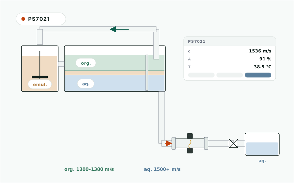
【Discriminator: working solution vs aqueous phase】

The Duty

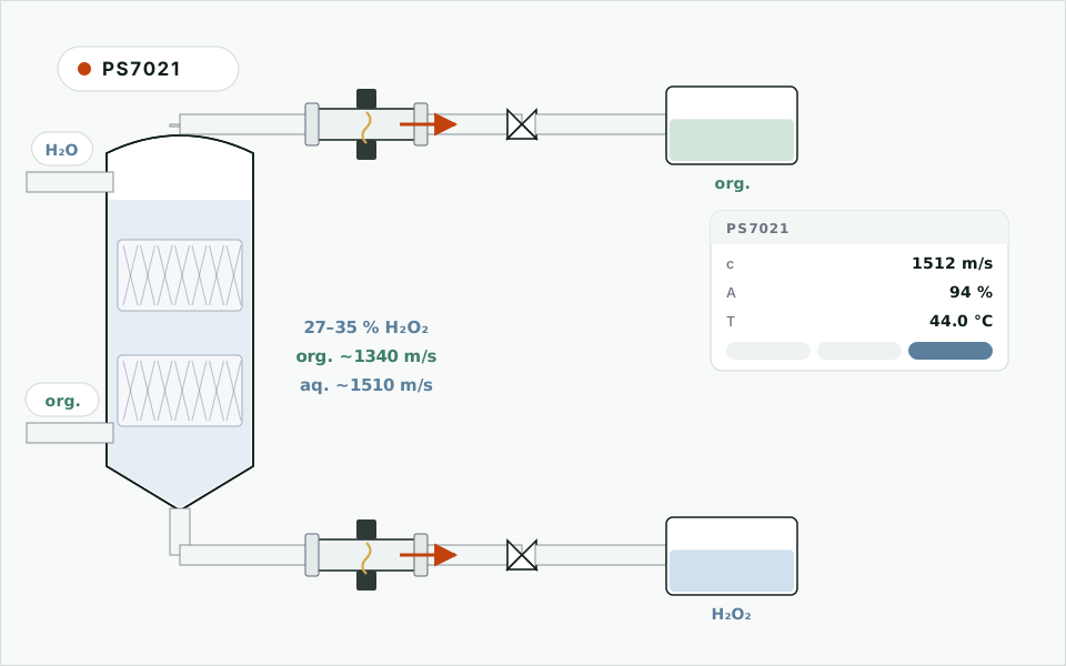
The anthraquinone loop runs hydrogenation → oxidation → extraction → work-up. The extraction column washes the oxidised working solution with demineralised water, pulling hydrogen peroxide into the aqueous phase: 27 to 35 % H₂O₂ leaves the bottom for purification, and the raffinate — the working solution, anthraquinone in heavy aromatics with a phosphate-ester co-solvent — goes back through drying to hydrogenation. One question runs through it: which phase is in this line right now.

A sight glass and an operator usually answer it. The trouble is that the two directions of carry-over do not cost the same:

DirectionConsequence
Working solution follows the aqueous phaseOrganics in the peroxide product: TOC and organic impurities off-spec, more load on purification, a downgraded batch at worst
Aqueous phase (carrying H₂O₂) returns with the working solutionPeroxide enters drying and hydrogenation. That is a safety problem, not a quality one — peroxide decomposes exothermically on catalyst and metal ions

So the instrument's failure direction has to be stop and wait for a human, never a confident wrong call.

Is the Gap Wide Enough

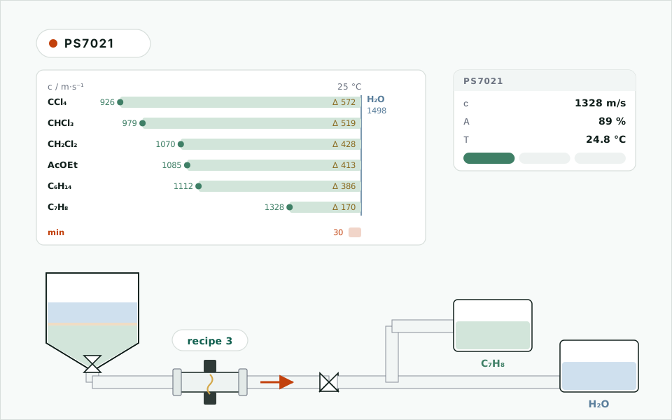
The working solution is a formulation and differs plant to plant, so the bands have to be measured on a sample. The magnitude is not in doubt, though: heavy aromatics sit with toluene and xylene (handbook values at 25 °C, 1328 and 1343 m/s), while the column's aqueous phase is peroxide solution in the 1500 m/s range (pure water at 25 °C is 1497 m/s, and peroxide solutions run slightly higher with concentration). That is over 150 m/s apart — five times the 30 m/s floor.

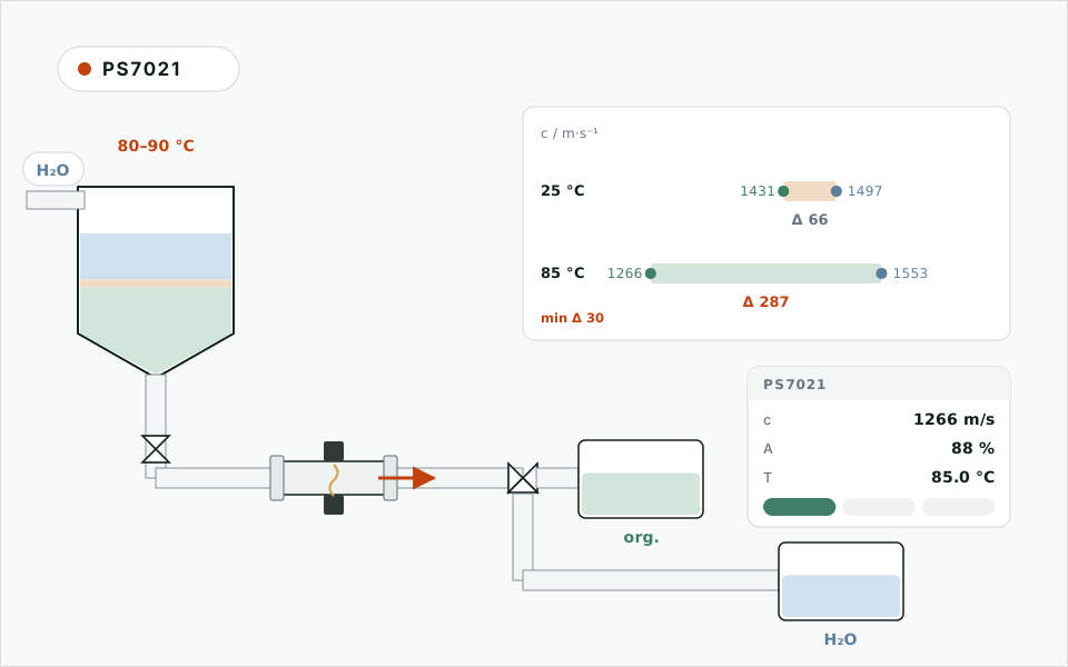
Extraction columns typically run at 40 to 50 °C, which helps: the organic coefficient is negative (aromatics about −4 m/s per °C) and water's is positive, so the bands spread as the column warms.

Materials in a Peroxide Plant

This is the one place where this duty differs from ordinary extraction. Hydrogen peroxide decomposes on rust, copper and its alloys, and rough surfaces, so the wetted side follows stricter rules than a normal solvent line:

  • Wetted parts are passivated 316L, PTFE/PFA and sapphire only; no copper, no carbon steel, no copper-bearing braze anywhere in the run
  • Sapphire (α-Al₂O₃) is inert to peroxide, so the window itself adds no risk
  • No dead legs or pockets in the spool — gas from decomposition collects there, and the first thing it costs you is the reading
  • Passivate with the plant, and do not weld or grind the line after passivation
  • PTFE or FFKM seals; ordinary elastomers have no business on this line anyway

Where It Goes

  • Raffinate separator outlet — the working-solution return, watching for aqueous carry-over
  • Column bottom — peroxide solution to purification, watching for working-solution carry-over
  • Around the purification column — the same two-phase question on both sides
  • All of them need a full line; on horizontal runs the path goes across the horizontal. When decomposition gas appears, the amplitude falls and the instrument reports not-decidable — on this duty that is exactly the wanted behaviour

What It Does Not Do

  • It does not measure peroxide concentration. That is a different curve; for concentration use PS7020, calibrated for H₂O₂
  • It does not track working-solution ageing — that is colour and composition, the province of inline colour or spectroscopy
  • It does not quantify entrainment in ppm. It answers which phase, not how much

To quote this duty we need: the working-solution family (aromatic plus which phosphate ester), the H₂O₂ concentration range, operating temperature, line size and material, whether the line has been passivated with the plant, the distance to the diverter, and the area classification. Send 500 mL of working solution and we will measure one band; the aqueous band we can make up to your concentration.
FAQ

Dichloromethane is far denser than water — why not use a density or acoustic-impedance meter?

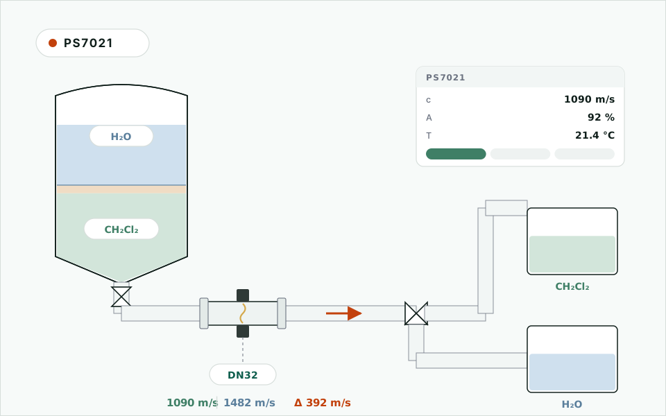
Because an ultrasonic density meter reads acoustic impedance, Z = ρ × c, not density, and dichloromethane happens to be dense and acoustically slow, so the two factors cancel. At 20 °C water is 1.48 MRayl and DCM about 1.45 MRayl, and between roughly 15 and 20 °C they coincide — which is where most plants separate. Inferred against water's velocity, DCM reads about 0.98 g/cm³: lighter than water, the wrong way round.

The same pair differs by 390 m/s in sound velocity (1482 against 1090 m/s, about 26 %), with opposite temperature coefficients, so warming widens the gap. That is why this duty takes the sound-velocity model (PS7021) rather than the impedance one (PS7000). DP and Coriolis meters do read true density and can separate the pair in principle, but they cannot keep up with a draining batch.

How is the rag layer handled — can it be mistaken for the aqueous phase and let through?

The rag layer is a third state, not a grey zone between two. Two quantities catch it.

First, velocity: a dispersion falls between the two bands (Wood's equation, first order, puts 30 vol% DCM near 1338 m/s and 50 vol% near 1256 m/s), and anything outside the clear-phase bands is not reported as a clear phase. Second, and more decisively, amplitude: droplet scattering weakens the echo, and 6 dB below the clear-phase baseline is reported as emulsion / not-decidable by default.

The interlock direction is fixed: on emulsion the instrument holds the valve and raises an alarm rather than switching. It will stop and wait for an operator before it lets a rag layer pass as either phase. The emulsion itself is a separation problem; what the instrument can do is refuse to wave it through.

Our line is DN32 and PTFE-lined — can this be fitted, and what happens at the liner?

Yes. DN32 is one of the standard bores (DN25 / DN32 / DN50). The lined build is a steel shell with a PTFE/PFA liner and sapphire windows that pass through the liner and wet the process.

Measuring through the liner is not an option: PTFE is 2.97 MRayl and strongly attenuating, and the bond between liner and shell changes with temperature and permeation — that turns a fixed acoustic path into a drifting one.

Two ordinary lined-pipe rules also apply. Wetted seals are PTFE or FFKM; ordinary FKM rates only fair against methylene chloride. And the shell's vent holes must stay clear — chlorinated solvents permeate fluoropolymer liners slowly, and trapped permeate lifts the liner off the wall.

Against conductivity and photoelectric (sight-glass) detectors — when should each be chosen?

Choose by whether the premise holds; each method rests on one.

Conductivity assumes the aqueous phase conducts, the organic does not, and an electrode may wet the process. Where that holds it is the cheapest answer. Pure-water washes, wet organics and lined pipe that is awkward to tap all soften it.

Photoelectric / sight glass assumes an optical difference. Turbidity- and colour-based units fail outright on dichloromethane and water — both are clear and colourless — while a refractive-index unit does work (1.424 against 1.333). Both share one weakness: a fouled window.

Sound velocity (PS7021) rests on two conditions only: the phases differ by at least 30 m/s, and the pipe runs full. It is independent of colour, turbidity, conductivity and density, which is why it holds where both phases are clear, both are non-conducting, or the aqueous conductivity moves. The price is a two-phase calibration on site, repeated at product changeover — five minutes, but somebody has to do it.

The item-by-item comparison is here.

Does commissioning need a shutdown, and how are the samples taken?

No shutdown. Calibration needs two velocity bands, and both samples come out of a normal batch: one while the light phase is running steady, one while the heavy phase is, 200 mL or more each. The instrument reads them itself — nothing goes to a lab. It usually fits inside one batch.

Three cautions: sample at process temperature (velocity is temperature sensitive, organics run −3 to −4 m/s per °C); draw the sample near the measuring point; and take the aqueous phase at its real salinity — clean water is not a substitute.

What you end up with is a velocity-versus-temperature table for both phases, delivered with the instrument. If the process temperature changes later, the thresholds shift along that table without a service visit.

How do the three relays drive a diverter valve, and which way does it fail?

Three volt-free contacts carry heavy, emulsion and light. The usual wiring: heavy closed → diverter to the heavy receiver; light closed → light receiver; emulsion closed → hold the current position and alarm for an operator to confirm.

The failure direction is the first thing to settle. Gas, flashing and window film all push the instrument toward not-decidable rather than toward the other phase, so making not-decidable mean stay put runs with the grain of the disturbances. Defaulting it to either phase turns every disturbance into a carry-over incident.

Keep the manual mode and the existing sight glass: the instrument supplies the judgement, not the valve. 4-20 mA trends velocity in the DCS; RS485 exposes phase, velocity, amplitude and temperature for the batch record.

How is it accepted on site — what do you compare it against?

The output is a phase decision, not a concentration you can compare against a titration, so acceptance looks different from a concentration meter's. Three workable tests:

1. Timing against the operator. Run a number of batches and align the instrument's switch instant with the operator's call at the sight glass. The site sets the tolerance; what usually matters is whether the instrument is ever late, since late means carry-over.

2. Sampling around the cut. Draw a sample either side of the instrument's switch instant and check that carry-over sits inside process limits.

3. The velocity itself. Measured band values should match the calibration table, and batch-to-batch drift in one phase should stay within the repeatability seen at calibration (±0.2 m/s). This is the test that separates "the instrument drifted" from "the material changed".

Can it measure how thick the rag layer is, or where the interface sits in a tank?

No — those are different instruments. PS7021 is an inline spool and knows only what is crossing its acoustic path right now: heavy, emulsion or light.

Interface height in a tank or settler belongs to an interface level instrument (magnetostrictive, radar, ultrasonic level, capacitance), mounted on the vessel rather than in the line. Rag layer thickness is the same question.

There is a useful indirect answer, though: time the instrument spends in the emulsion state during a drain, multiplied by flow, gives the volume of rag in that batch. It is not an interface height, but as a trend for how well the break worked or whether settling time is enough, it is often the more direct number.

Does it need a straight run? Can it go right after a pump or a control valve?

No straight run is required. The path length is fixed by the spool and the discriminators are velocity and amplitude, which do not care about the flow profile — unlike DP, vortex or magnetic meters, which live on it.

The position still matters, but for a different reason: phase and gas. Pump discharges, the downstream side of control valves and other throttling points generate gas or flashing continuously, which holds the amplitude down and degrades three-state discrimination. Mount upstream of them, or further downstream where the flow has settled.

Three other rules: a full line is not negotiable; on horizontal runs put the path across the horizontal (3 and 9 o'clock), away from gas at the top and solids at the bottom; and keep the measuring point close to the diverter, because that hold-up is the mixed volume every batch pays.

What about high temperature, sanitary execution and CIP?

Temperature: −20 to +80 °C standard, −20 to +120 °C for the high-temperature variant. Heat actually helps the discrimination: organic velocity falls with temperature while water rises below 74 °C, so the bands spread. Edible oil washing at 80-90 °C is the textbook case.

Sanitary: the standard spool is industrial and flanged. Tri-clamp, polished bore and drainable geometry are a custom build with their own lead time and price — say so at selection rather than assuming the standard spool can enter a sanitary zone.

CIP: the sapphire window is dense and smooth, so hot caustic, hot water or solvent all clean it in place. Compare the amplitude baseline before and after and you know whether the clean worked — far easier than scheduled teardown.

Can it still work if the line carries solids or crystals?

It depends on the load. A light suspension does not move the velocity reading but scatters sound and lowers the echo amplitude — and amplitude is what catches the rag layer, so with heavy solids three-state discrimination degrades to two: light and heavy still separate, emulsion and "solids present" no longer do.

In practice: put the point after settling, filtration or a steady pump; at commissioning re-baseline the amplitude against the real solids-bearing fluid rather than against clear liquid; and if solids content is itself the quantity you want, that is another instrument — PS7000 and the acoustic-impedance method.

Crystals add one more wrinkle: they grow a film on the window. The film shows in the amplitude baseline first, which makes that baseline a useful clean-me reminder.

How wide does the velocity gap have to be, and can it be estimated first?

The floor is 30 m/s at working temperature. Common organic-against-water pairs are far above it: carbon tetrachloride is 572 m/s from water, dichloromethane 428, ethyl acetate 413, toluene 170, m-xylene 155 (handbook values at 25 °C). For those the gap is never the constraint.

Three cases do need arithmetic first: oil against oil (diesel and kerosene are 74 m/s apart), oil against water at ambient (edible oil and water, about 66), and formulated fluids — peroxide working solution, SX organic, a demulsified waste oil.

How to estimate: take handbook values at 25 °C, carry both to working temperature with their coefficients (organics −2.7 to −4.9 m/s per °C, water about +2.4 below 74 °C), then add salt on the aqueous side (roughly +11 m/s per wt% NaCl). Above 100 m/s you are safe; 30 to 100 needs a measurement; below 30, don't.

How many products can one instrument cover, and does a changeover need recalibration?

Eight recipes as standard, each holding a pair of velocity bands and its amplitude threshold; the list extends. Switch from the panel, or let the DCS write a Modbus register — the second follows the batch instruction and removes the "nobody switched it" class of incident.

A product that has never been calibrated needs one pass: two samples, two readings, one stored pair — five minutes, no return-to-factory sampling. Coming back to a known product just recalls its recipe.

When to redo an existing recipe: the composition of that phase moved (water content, salt, product concentration), the temperature band shifted, or acceptance found measured velocity off the stored band by more than the repeatability. Every recalibration records its time and both velocities for the batch record.

How often does the sapphire window need cleaning, and how do you know?

No fixed interval — it depends on the duty. What actually helps: the instrument tells you.

As film, crystal or oil builds on the window, the velocity reading does not move at first, but the amplitude baseline drifts down. Trend the clear-phase baseline: a slow decline means clean it; a sharp drop with velocity still in band is an emulsion slug passing, not deposit. The two shapes are easy to tell apart on a trend.

How to clean: sapphire is dense and smooth, so hot caustic, hot water or a normal solvent will do it, usually in place. On duties that will certainly film — edible oil, spent emulsions — put it on the CIP schedule. Afterwards check whether the amplitude baseline came back: that is the acceptance test for the clean.