A glass-fibre sizing-agent plant in eastern China replaced manual sampling and oven-drying with an inline density meter to track solids content. The medium is an emulsion blended from a dozen or so chemical feedstocks, dispersed phase 0.2–0.8 μm, solids typically around 8.5 %, on a self-circulating loop running about 20 kg/min.
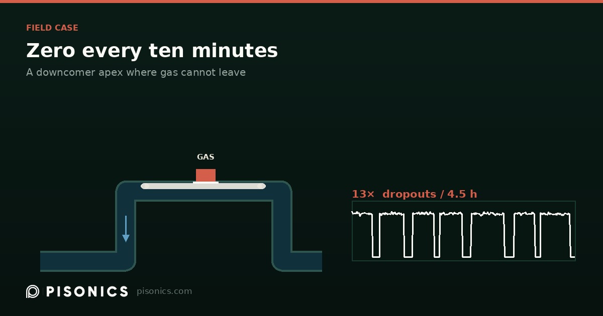
The symptom was oddly regular. The reading would track normally, then collapse to zero, then recover on its own anywhere from a few seconds to a few minutes later. The plant's first assumption was an instrument fault.
Look at the data before forming a theory
We pulled 4.5 hours of logged data and wrote a script to detect the dropout segments automatically:
- 13 dropouts, all between 09:59 and 13:08
- Median interval 10 minutes, longest gap 31 minutes
- Individual dropouts lasted 0.2 to 8.8 minutes
- Peak echo-energy fluctuation during dropouts averaged about 108 mV, against roughly 49 mV the rest of the time — a factor of 2.2
- After 13:08 there were no dropouts for 77 consecutive minutes, and probe temperature rose noticeably over the same period
That last point matters. Rising probe temperature usually means flow has stopped. A "fault" that only occurs during certain periods and correlates with flow state is generally not a fault.
Two hypotheses that were eliminated
The site initially suspected two things, both of which the customer later corrected:
A ruptured diaphragm admitting compressed air — but this is an electric diaphragm pump, not air-operated. There is no compressed air anywhere in the path.
The probe being starved on the pump suction side — but the probe is not on the suction side; that riser holds the suction-side basket strainer.
With both eliminated, the remaining evidence pointed at the mounting geometry itself.
The actual cause: gas gets in and cannot get out
The probe was mounted at the top of the return downcomer — the highest point of the whole loop — with flow running downward through it.
For DN50, downward velocity works out to roughly 0.17 m/s. Fine bubbles are carried in with the liquid, but they coalesce in the low-velocity zone at the crown. Once a bubble grows to millimetre scale, its buoyant rise velocity exceeds the 0.17 m/s downward flow — it can get in, but it cannot get out.
The pocket grows until it blocks the acoustic path. The interface the probe sees is no longer slurry but gas, the primary variable clamps to the bottom of the range, and the display reads zero. Occasionally a flow surge carries the whole pocket away and the reading recovers within seconds — which is exactly the square-wave shape observed.
Remedies, in order of cost-effectiveness
- A|Extend the return pipe outlet below the liquid surface — reduce entrainment at source
- B|Move the probe to the vertical upward-flow section on the pump discharge, with at least 10D of straight run upstream. On an upward leg, bubbles rise in the same direction as the flow and leave on their own
- D|Fit an automatic air-release valve at the high point
None of these touch the instrument or require recalibration.
There is also a zero-cost way to confirm the mechanism: fit a manual bleed valve at the apex. Next time the reading drops, open it. If gas comes out and the reading recovers at the same moment, the diagnosis is proven.
The transferable lesson
The high point of a pipe run, the apex of a downcomer, and any geometry where gas enters but cannot leave are all unsuitable for an inline density meter — whatever the measuring principle. What makes these positions dangerous is that the instrument does not report an error. It gives you a stable-looking wrong number.
Pisonics — Xi'an Pisonics Information Technology Co., Ltd.
Room 15B016, 16F, Block A, Olympic Building, No.14 Chang'an North Road,
Beilin District, Xi'an, Shaanxi 710061, China
+86 159 0293 2017 | info@pisonics.com | www.pisonics.com
Send us pipe size, velocity, particle size distribution and whether the line
carries entrained air, and we will tell you which principle fits your line —
including the cases where ours does not.